CHAPTER 3 - INSTALLATION AND CONNECTION
56
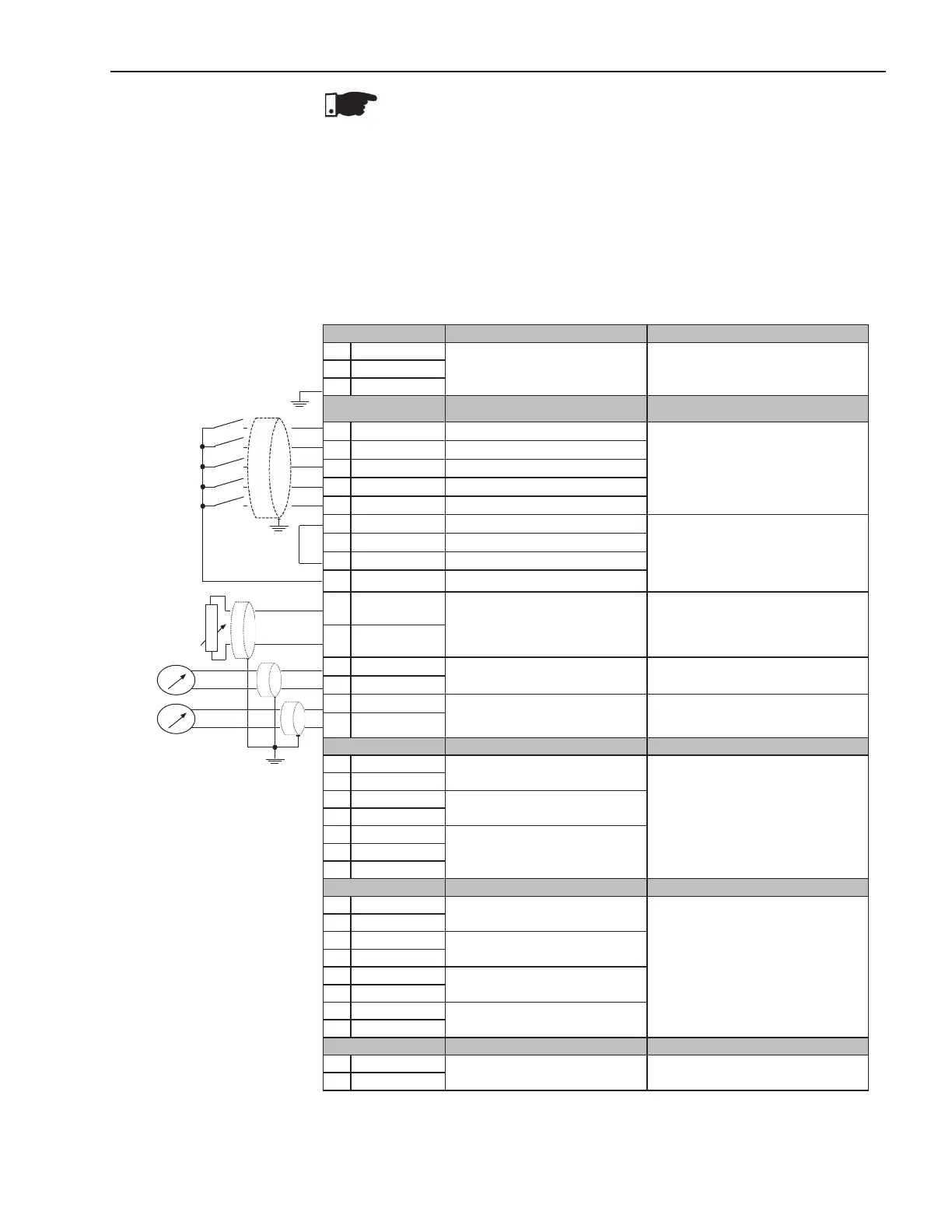
3.2.8 Signal and Control
Connections
The signal connections (analog outputs) and control (digital inputs and
relay outputs) are made on the electronic board connectors.
Connectors:
CCS6 and CPS61 on the models 10A to 30A. CCS6 and CPS63 or CPS66
on the models 45A to 365A and 950A to 1400A. CCS6 and CPS64 or
CPS65 on the models 412A to 820A.
Note: NC = Normally Closed Contact
NO = Normally Open Contact
C = Common
Figure 3.16 - Control Terminal Description
NOTE!
For models from 255A to 820A the fans are switched on if the heatsink
temperature is above 70ºC (158ºF). Do not forget to connect the fan
power supply and select the fan supply voltage for the models higher or
equal than 255A.
PTC
Connector X1A Description Specications
1 Phase
Electronic Supply
(110 to 230)Vac (-15% to +10%) or (94
to 253)Vac
Operation Current: 280mA Max.
2 Neutral
PE Ground
Connector X1B Factory Standard Function Specications
3 DI1 Motor Enable/Disable
5 isolated digital inputs
Minimum high level: 18Vdc
Maximum low level: 3Vdc
Maximum voltage: 30Vdc
Input current: 11mA@24Vdc
4 DI2 Error Reset
5 DI3 Not Used
6 DI4 Not Used
7 DI5 Not Used
8 COM Common point of the Digital Inputs
Only use for Digital Inputs
9 COM Common point of the Digital Inputs
10 DGND 0V reference of the 24Vdc source
11 24Vdc Digital Input Supply
12 PTCB
DI6 - Not Used
Input for motor Thermistor
Operation:3k9ΩRelease:1k6Ω
Minimum resistance: 100
PTCB referenced to DGND
Through249Ωresistor
13 PTCA
14 AGND
Analog Output 1 - Not used
(0to10)V,RL10k(maximumload)
Resolution: 11 bits
15 AO1
16 AGND
Analog Output 2 - Not used
(0 to 20)mA or (4 to 20)mA
RL=500Ω/1%@10V
Resolution: 11 bits
17 AO2
Connector X1C Factory Standard Function Specications
18 RL1NO
Relay Output - Run
Contact capacity:
1A
240Vac
19 RL1NO
20 RL2NO
Relay Output - Full Voltage
21 RL2NO
22 RL3NO
Relay Output – No Error23 RL3C
24 RL3NC
Connector X1D Description Specications
25 TERM.
Overtemperature thermostat
Internal connection of the Soft-Starter
26 TERM.
27 TC 1/R RED
Current transformer phase R
28 TC1/RBLACK
29 TC 2/S RED
Current transformer phase S
30 TC2/SBLACK
31 TC 3/T RED
Current transformer phase T
32 TC3/TBLACK
Connector X1E Description Specications
33 Phase
Fan Supply (from model 255A)
(104 to 127)Vac or (207 to 253)Vac
Operation current: see table 3.4
34 Neutral