CHAPTER 3 - INSTALLATION AND CONNECTION
57
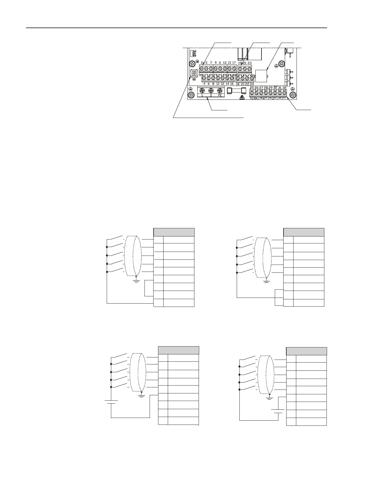
Figure 3.17 - Control connector positions
Figure 3.18 - Connection diagram of the digital inputs using the auxiliary internal source
Figure 3.19 - Connection diagram of the digital inputs using an external source
For signal and control wire installation, adopt the following
procedures:
1) The connections of the SSW-06 digital inputs can be carried out
in several ways. They can be supplied by auxiliary internal +24Vdc
source by using the 0V as a common point or by the +24Vdc source.
Depending on the application requirements,they can also be supplied
byexternal+24Vdcsource,connectedtoPLCs,byusingthe0Vas
common point or by the +24Vdc source:
Connector X1B
3 DI1
4 DI2
5 DI3
6 DI4
7 DI5
8 COM
9 COM
10 DGND
11 24Vdc
Connector X1B
3 DI1
4 DI2
5 DI3
6 DI4
7 DI5
8 COM
9 COM
10 DGND
11 24Vdc
Connector X1B
3 DI1
4 DI2
5 DI3
6 DI4
7 DI5
8 COM
9 COM
10 DGND
11 24Vdc
Connector X1B
3 DI1
4 DI2
5 DI3
6 DI4
7 DI5
8 COM
9 COM
10 DGND
11 24Vdc
To be used for grounding of shield of
the signal and control cables
XO
X1A
X1B X1C X2
X1D
24Vdc
+
24Vdc
+