CHAPTER 3 - INSTALLATION AND CONNECTION
58
Table 3.13 - Wiring separation distances
If the crossing of these cables is unavoidable, install them perpendi-
cular, maintaining a minimum separation distance of 5cm (2 in) at
the crossing point.
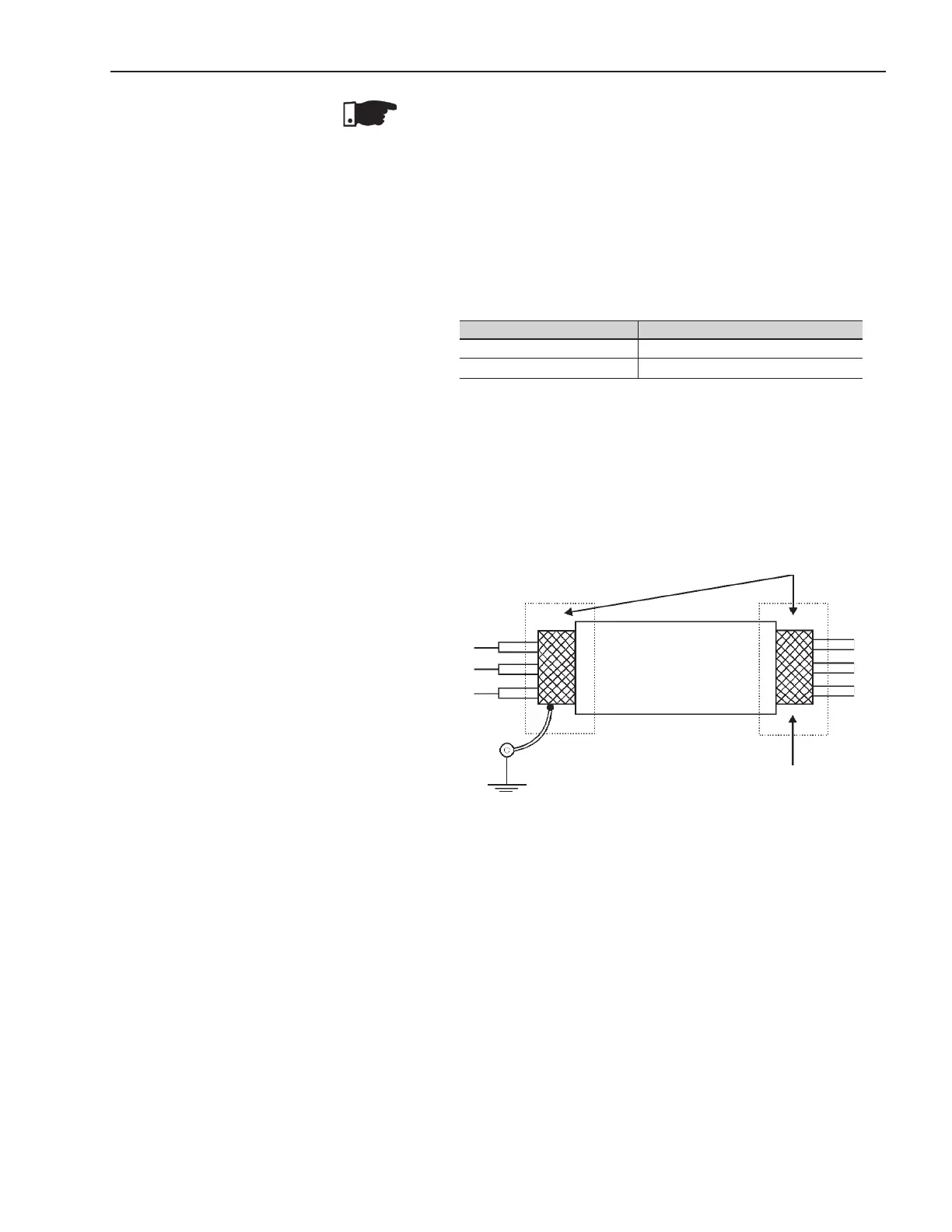
Connect the shield as shown below:
6) For wiring distances longer than 50m (150ft), it is necessary to use
galvanic isolators for the X1B:3...17signals.
7) Relays, contactors, solenoids or electromagnetic braking coils
installed near Soft-Starters can generate interference in the control
circuit. In order to eliminate this interference, connect RC suppres-
sors in parallel with the coils of AC relays. Connect a free - wheeling
diode in case of DC relays/coils.
8) When an external keypad is used (Refer to Chapter 9), separate
the cable that connects the keypad to the Soft-Starter SSW-06
from other cables, maintaining a minimum distance of 10cm (4 in)
between them.
This connector is used to make a standard RS-232 communication
WiringLength Min.separationdistance
≤ 30 m (98.4 ft) ≥ 10 cm (3.94 in)
> 30 m (98.4 ft) ≥ 25 cm (9.84 in)
Insulate with tape
Do not ground
Soft-Starter side
Connect to ground
Screw located on the CCS6 board
Figure 3.20 - Shield connection
NOTE!
1) The auxiliary electronic power supply of the SSW-06 Soft-Starter
of +24Vdc shall only be used for the supply of the digital inputs.
2) The SSW-06 Soft-Starter factory default is with the pins 8 and 10
of the X1B connector bridged (wire bridge).
3) Cable cross section (0.5 to 1.5) mm
2
.
4) Maximum torque: 0.50 N.m (4.50 ibf.in).
5) X1B wiring must be connected with shielded cables and installed
separately from other wiring (power, control at 110V/220V, etc.),
according to table 3.13.