CHAPTER 3 - INSTALLATION AND CONNECTION
59
AnoptionalProbusDPorDeviceNetCommunicationboardcanbe
attached to this connector.
FormoredetailsseetheProbusDPorDeviceNetCommunication
Manual of the Soft-Starter SSW-06 and chapter 9.
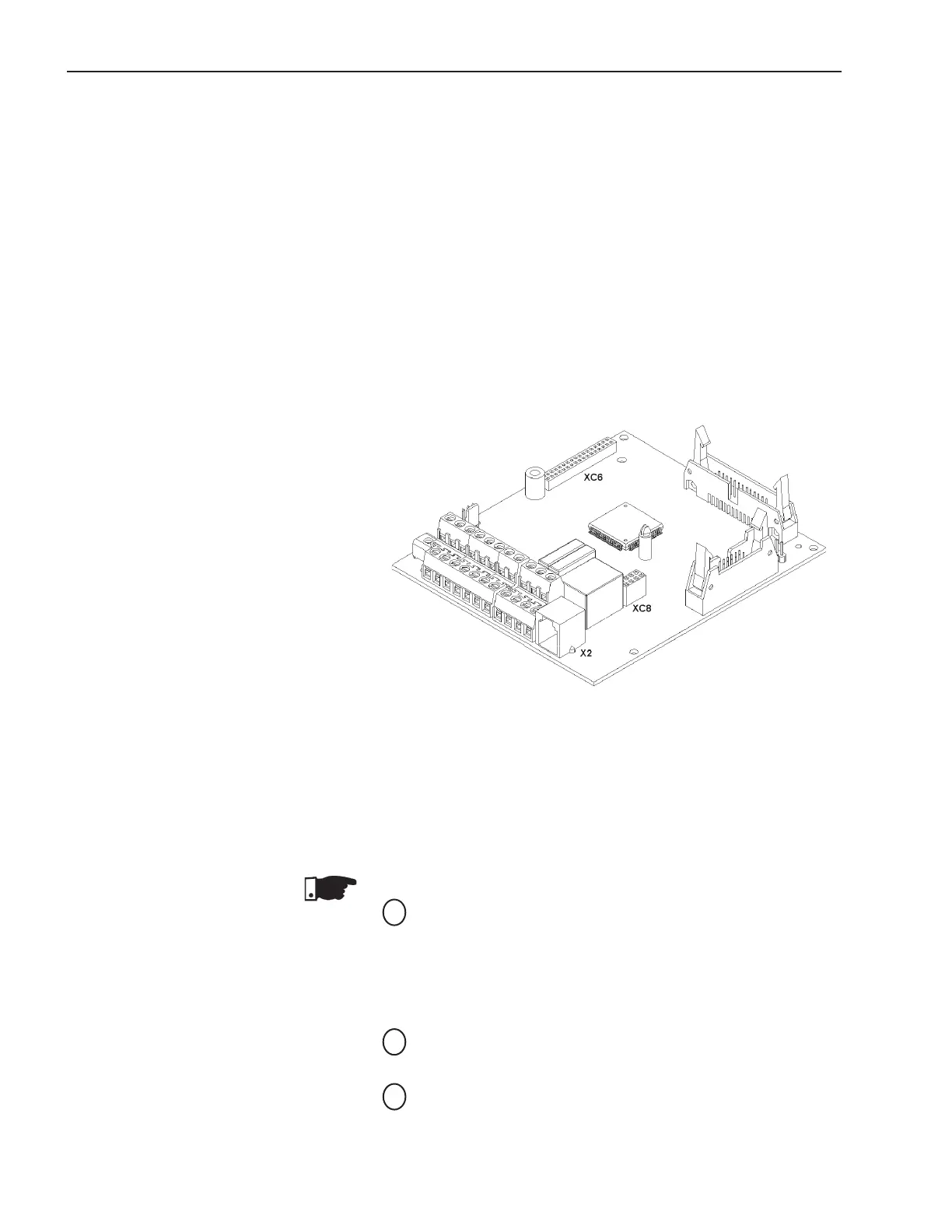
3.2.11 XC6 Fieldbus
Communication Board
Connection
Figure 3.21 - X2, XC6 and XC8 Connector
3.3 RECOMMENDED
SET-UPS
In this item some suggestive set-ups are presented, which can be
used completely or in part to elaborate the desired control.
The main warnings, for all the suggestive set-up, listed below, are
related in the diagrams through their respective numbers.
NOTES!
For the protection of all of the electrical installation, the use
of fuses or circuit breakers in the main power supply circuit is
necessary.
The use of high speed semiconductor fuses are not necessary
for the functioning of the SSW-06 Soft-Starter, but its use is
recommended for the complete protection of the SSW-06.
The transformer “T1” is optional and should be used when the
linevoltageisdierentfromtheelectronicsandfanvoltage;
To protect the motor against destruction by possible short-
circuits in the power circuit of the Soft-Starter SSW-06 use an
isolating contactor (K1) or circuit-breaker (Q1);
3.2.9 RS-232, X2 Serial
Communication Connection
3.2.10 XC8 Serial
Communication Board
Connection
linebetweentheSoft-StarterSSW-06andaPCand/orPLC.
For more details see the Serial Communication Manual of the
Soft-Starter SSW-06.
An optional board of serial communication, standard RS-485 with
galvanic insulation, or USB, can be attached to this connector.
For more details see the Serial Communication Manual of the
Soft-Starter SSW-06 and chapter 9.
1
2
3