CHAPTER 3 - INSTALLATION AND CONNECTION
66
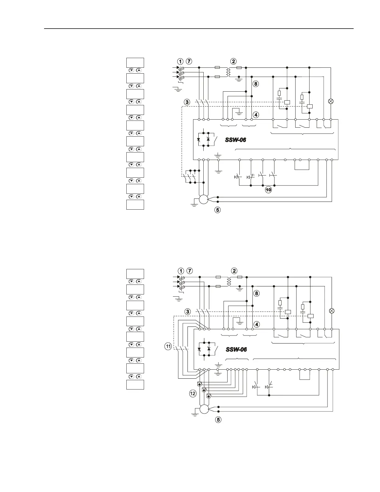
3.3.11 Recommended Set-up with Command via Digital Inputs and DC-Braking
Figure 3.32 - Recommended Set-up with Command via Digital Inputs and DC-Braking
3.3.12 Recommended Set-up with Command via Digital Inputs and External By-pass Contactor
Figure 3.33 - Recommended Set-up with Command via Digital Inputs and External By-pass Contactor
+ t
o
M
3~
R
S
T
PE
K1
R S T
1 2 PE
33 34
X1EX1A
18
19
RL1 RL2
20
21
22
23
24
RL3
X1C
X1B
Dl1
3
Dl2
4
Dl3
5
Dl4
6
Dl5
7
COM
8 9
0V
10
24V
11
PTC
B A
12 13
U V W
Fault
T1
K1
PTC
Start
Stop
K2
Without
Braking
Gen. Enable
K2
+ t
o
M
3~
R
S
T
PE
K1
R S T
1 2 PE
33 34
X1EX1A
18
19
RL1 RL2
20 21
22
23
24
RL3
X1C
X1B
Dl1
3
Dl2
4
Dl3
5
Dl4
6
Dl5
7
COM
8 9
0V
10
24V
11
PTC
B A
12 13
U V W
Fault
T1
K1
PTC
Start
Stop
K2
K2
X1D
27
28
29
30
31
32
Red
Black
Black
Red
Black
Red
See notes in the item 3.3
See notes in the item 3.3
P265 =1
P264 =1
P230 =1
P220 =1
P266 =5
P277 =1
P279 =6
P500 =3
P278 =5
P263 =2
P264 =1
P230 =1
P220 =1
P140 =1
P277 =1
P278 =3
P279 =6
P263 =2