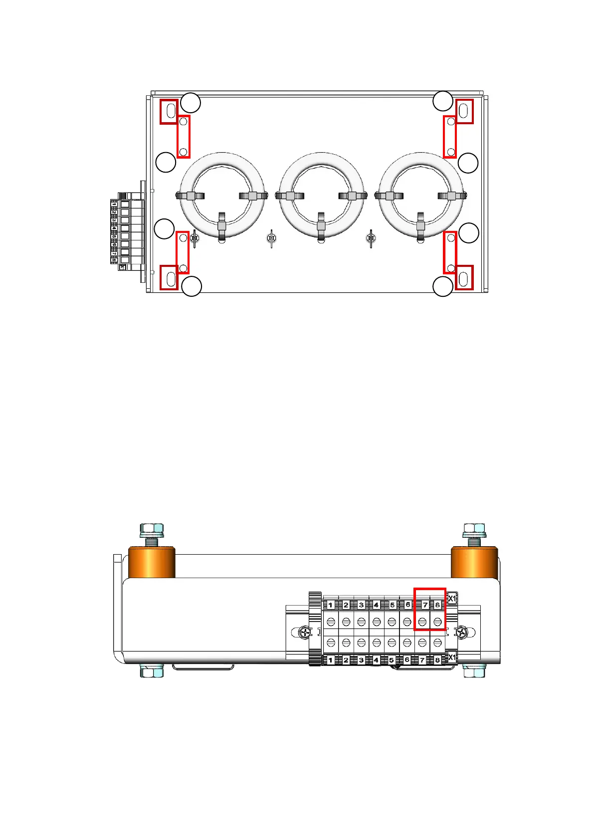
1 - Holes to fix the ground fault CT (optional).
2 - Holes to fix the isolators.
Figure 3: Base of the CTs with indication of the fixation and cable passage holes.
III. ELECTRIC CONNECTION
The terminals of the ground fault CT must be connected to the terminals 7 and 8 of the
connector installed on the CT base, as shown in figure 3. The connection to the medium
voltage control card - CSMx is made on terminals 31 and 32 of the connector XC4, as
shown in figure 4.
Figure 4: Terminals (7 and 8) to connect the cables of the ground fault CT.
3

 Loading...