7
1
21
4
51
51
14
Small
Holes
1
5
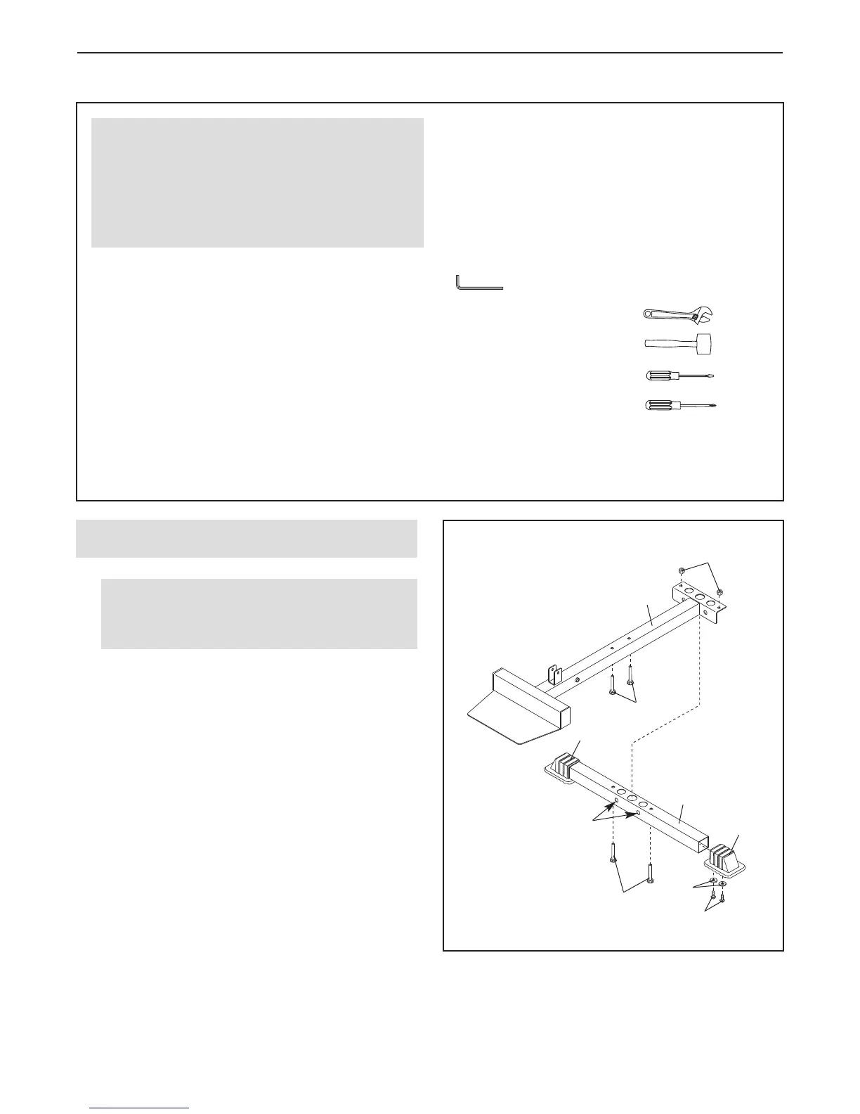
1.
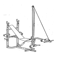
Attach a Stabilizer Foot (51) to the Stabilizer (5)
with two M4 x 20mm Screws (56) and two M4
Washers (82). Attach another Stabilizer Foot in
the same way.
Insert two M10 x 67mm Carriage Bolts (14) up
through the Stabilizer (5). Insert two M8 x 65mm
Carriage Bolts (1) up through the Base (4). Note:
It may be helpful to place a piece of tape over
the bolt heads to hold the Carriage Bolts in
place.
Orient the Stabilizer (5) so that the small holes
are on the indicated side. Attach the Base (4) to
the Stabilizer with the two M10 x 67mm Carriage
Bolts (14) and two M10 Nylon Locknuts (21). Do
not tighten the Nylon Locknuts yet.
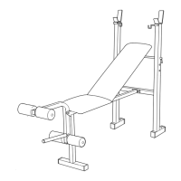
Frame Assembly
Before beginning assembly, make sure that
you have read and understand the informa-
tion in the box above.
ASSEMBLY
56
82
Before beginning assembly, carefully read the fol-
lowing information and instructions:
• Assembly requires two persons.
• Because of its size, the weight bench should be
assembled in the location where it will be used.
Make sure that there is enough clearance to walk
around the weight bench as you assemble it.
• Place all parts in a cleared area and remove the
packing materials. Do not dispose of the packing
materials until assembly is completed.
• Tighten all parts as you assemble them, unless
instructed to do otherwise.
• As you assemble the weight bench, make sure all
p
arts are oriented as shown in the drawings.
• For help identifying small parts, use the PART
IDENTIFICATION CHART on page 5.
• Assembly requires the included hex key(s)
and the following tools (not included):
two adjustable wrenches
one rubber mallet
one standard screwdriver
one Phillips screwdriver
Assembly may be more convenient if you have a
socket set, a set of open-end or closed-end
wrenches, or a set of ratchet wrenches.
M
ake Assembly Easier
Everything in this manual is designed to ensure
that the weight bench can be assembled suc-
cessfully by almost anyone. Set aside plenty of
time, so that assembly will go smoothly.