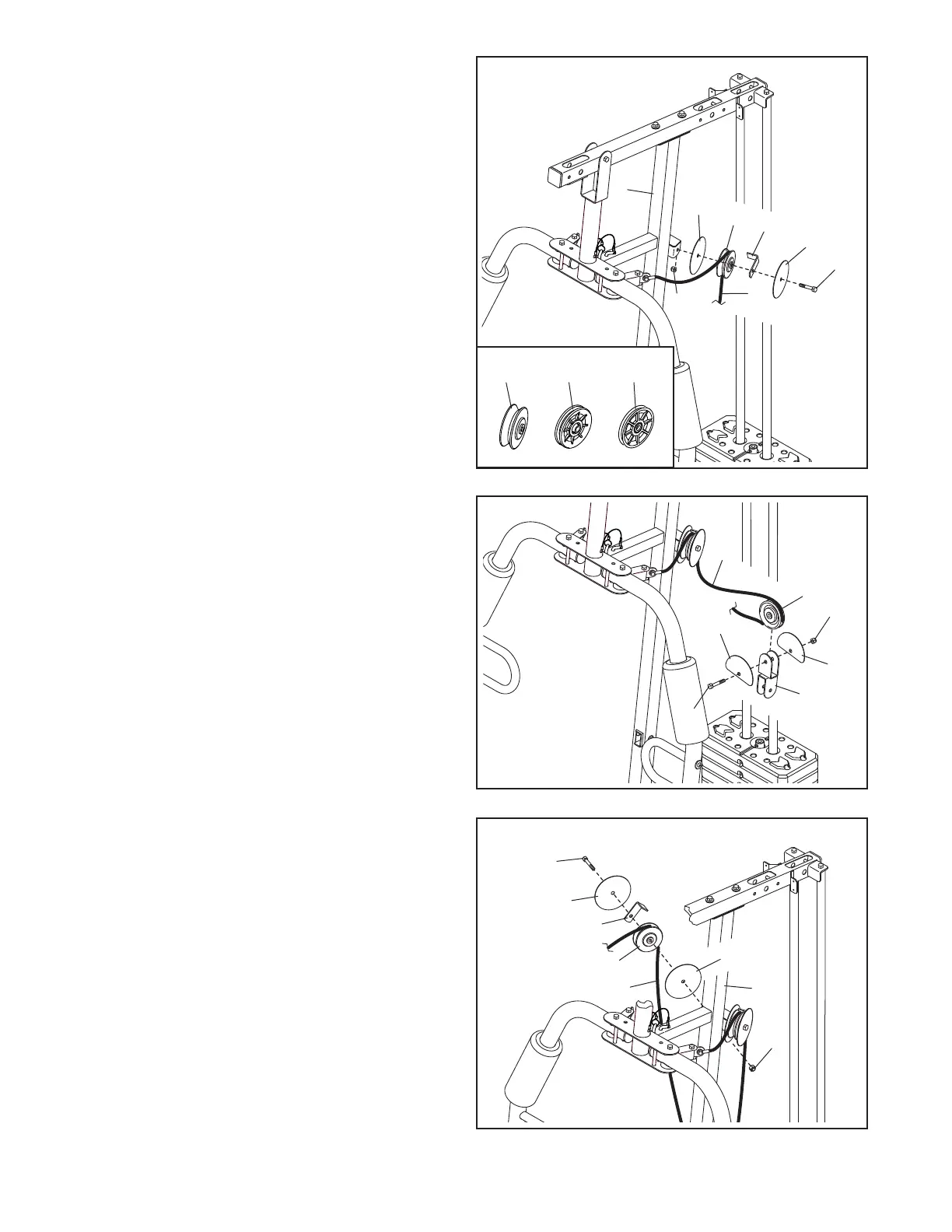
14
16. IMPORTANT: Identify the two V-pulleys (46),
the nine Thick Pulleys (48), and the two Thin
Pulleys (47).
Tip: It may be helpful to refer to the
EXPLODED DRAWING near the end of
this manual to identify the locations of the
pulleys.
Route the Arm Cable (54) over a V-pulley (46).
Attach the V-pulley (46), a Cable Trap (50), and
two Full Guards (41) to the Upright (3) with an
M10 x 63mm Bolt (75) and an M10 Locknut (56).
Make sure that the Cable Trap (50) is oriented
to hold the Arm Cable (54) in the groove of
the V-pulley (46).
56
3
46
50
41
75
54
41
16
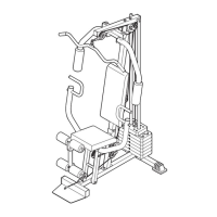
17. Route the Arm Cable (54) around a Thick
Pulley (48).
Attach the Thick Pulley (48) and two Half Guards
(43) to the Double U-bracket (63) with an
M10 x 45mm Bolt (81) and an M10 Locknut (56).
Make sure that the Half Guards are on the
outside of the Double U-bracket as shown.
48
43
43
63
56
54
17
18
56
3
46
50
75
54
41
81
41
18. Route the Arm Cable (54) over a V-pulley (46).
Attach the V-pulley (46), a Cable Trap (50, and
two Full Guards (41) to the Upright (3) with an
M10 x 63mm Bolt (75) and an M10 Locknut (56).
Make sure that the Cable Trap (50) is oriented
to hold the Arm Cable (54) in the groove of
the V-pulley (46).
48
47
46