14
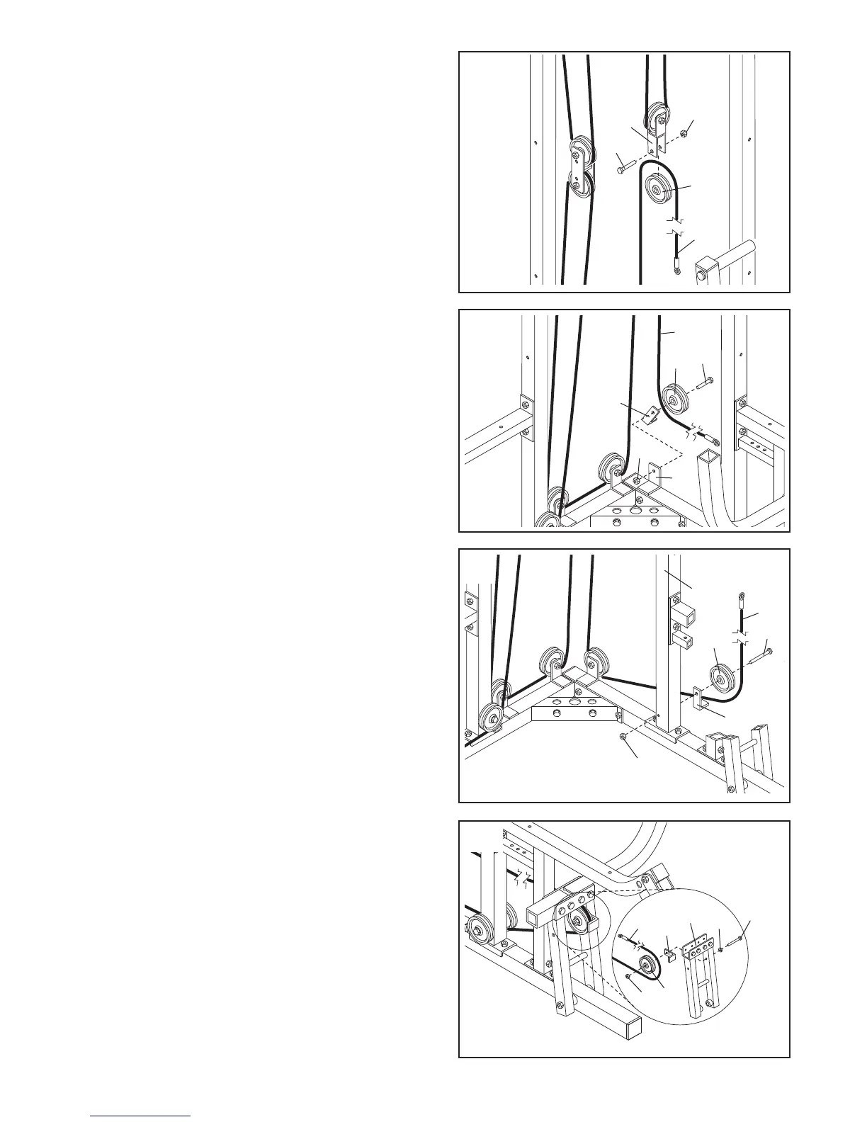
26. Wrap the Long Cable (73) around a 3 1/2” Pulley (5)
in the direction shown. Attach the Pulley and a Cable
Trap (39) to the indicated bracket on the Press Base
(60) with a 3/8” x 2” Bolt (35) and a 3/8” Nylon
Locknut (4). Make sure the Cable Trap is oriented
as shown.
27. Attach a 3 1/2” Pulley (5) and a Cable Trap (39) to
the Press Frame Upright (59) with a 3/8” x 4 3/4” Bolt
(23).
Wrap the Long Cable (73) around the 3 1/2” Pulley
(5) in the direction shown. Hand tighten a 3/8” Nylon
Locknut (4) two turns onto the 3/8” x 4 3/4” Bolt. In
step 31, another Pulley will be attached to the Bolt.
25. Note: For clarity, this and the following drawings
show some parts removed.
R
emove the lower 3 1/2” Pulley (5) from the Double
“U”-Bracket (36). Then, wrap the Long Cable (73)
o
ver the Pulley (5) in the direction shown. Attach the
Pulley to the Double “U”-Bracket (36) with a 3/8” x 1
3/4” Bolt (22) and a 3/8” Nylon Locknut (4). Make
sure the Double “U”-Bracket is oriented as
shown.
28. Route the Long Cable (73) through the opening in the
Press Frame (53) and wrap the Long Cable around a
3 1/2” Pulley (5) in the direction shown. Then, route
the Long Cable back through the opening in the
Press Frame.
Attach the 3 1/2” Pulley (5) and a Cable Trap (39) to
the indicated hole in the Press Frame (53) with a 3/8”
x 3 1/4” Bolt (28), a 3/8” Flat Washer (17), and a 3/8”
Nylon Locknut (4). Make sure the Pulley is mount-
ed on the inside of the Press Frame (53). Make
sure the Cable Trap is oriented as shown.
26
25
3
6
4
5
73
60
39
4
73
5
35
22
4
23
73
5
39
59
4
5
39
73
53
28
17
28
27