上海维宏电子科技股份有限公司
Weihong Electronic Technology Co., Ltd.
Specialized, Concentrated, Focused 5
3 Structure of Machining File
A machining file is a group of instructions and data transmitted to the CNC device, and it is
composed of program blocks which follow a certain structure, syntax and format rule, while each
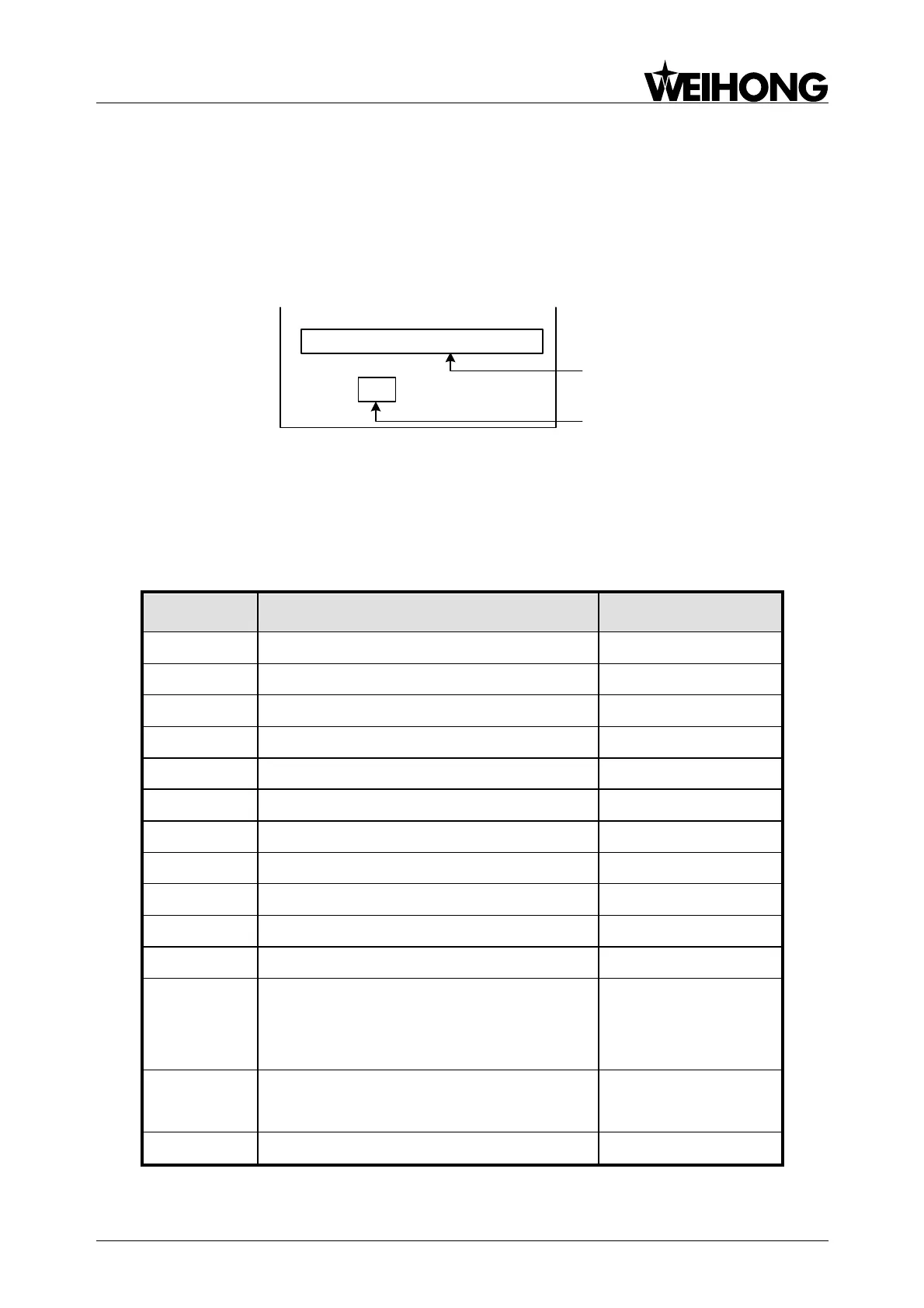
program block is composed of command words. See Fig. 3-1.
N01 G91 G00 X50 Y60
N10 G01 X100 Y500 F150 S300 M03
N……
N200 M02
Program
block
Command
word
Fig. 3-1 Program Structure
3.1 Address Symbols and Functions
Address symbols and definitions are as shown in Form 3-1.
Form 3-1 Address Symbols
B: Basic Function
O: Optional Function
Cutter radius offset number
Arc center modifier for X axis
Arc center modifier for Y axis
Arc center modifier for Z axis
Sequence no. or block no.
Dwell time in milliseconds, subprogram no.
call, custom macro no. call, block number in
main program when used with M99
Depth of peck in fixed cycles G73 and G83
Shift amount in fixed cycle G76 and G87
Retract point in fixed cycles