Specialized Concentrated Focused
Wiring「9」
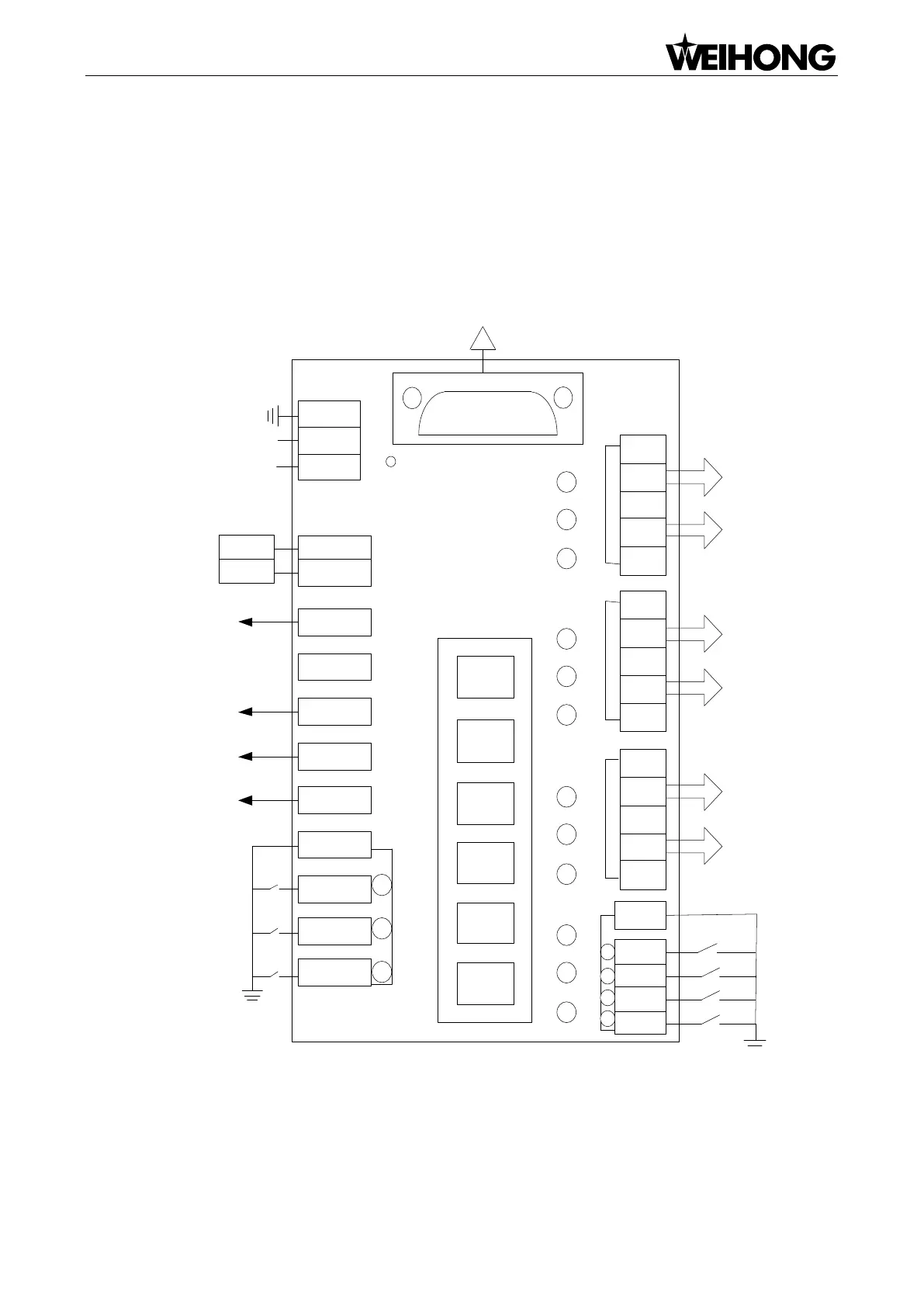
3.3 Wiring Diagram of Terminal Board
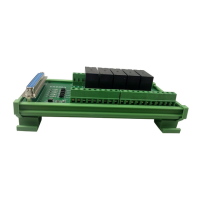
Terminal Board EX23A
See Fig. 3-7 for the wiring diagram of the terminal board EX23A (154mm*72mm), for standard XYZ
axes configuration for engraving machines.
SVC
GND
SPIN
Output
Relay
Area
DB37 Socket
POWER
AVI
ACM
+
SPCOOL
Y-0
Z-0
COM
X-0
ZD-
ZD+
ZP-
ZP+
+5V
X-axis Driver Interface
COM
START
CUT
STOP
ESTOP
Power Status Indicator
OIL
GREEN
RED
YD-
YD+
YP-
YP+
+5V
Y-axis Driver Interface
Y-axis Driver
XD-
XD+
XP-
XP+
+5V
Z-axis Driver Interface
X-axis Driver
Operation Inputs
GND
Cycle Stop
Cycle Start
Tool Sensor Signal
E-stop
Home Inputs
GND
Home (Y)
Home (X)
Analog
Output
Analog Voltage
Analog GND
24VDC
Power Input
PM53B/53C Motion Control Card
Spindle ON
Auto Lube
Green
Red
Home (Z)
EX23A3
COM
+24V
-
Z-axis Driver
Fig. 3-7 Wiring Diagram of Terminal Board EX23A