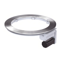
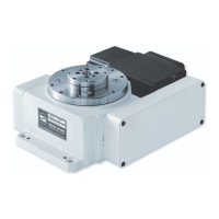
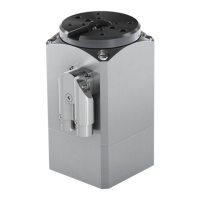
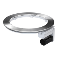
Rotary indexing ring TR
Maintenance
Mounting the inductive sensor
When the inductive sensor is installed, the
switching distance between the position cam
on the driving cam and the inductive sensor
must be adjusted. For this purpose, the posi-
tion cam must be located opposite the mount-
ing position of the inductive sensor (in the de-
tection area of the inductive sensor).
1. Look at the driving cam through the
opening in which the bushing of the limit
switch was previously installed.
2. Verify that the position cam [1] faces the
mounting position of the inductive sensor
[2].
If the position cam does not face the mounting position of the inductive sensor, you must pull the
toothed belt until the position cam is directly opposing the mounting position of the inductive sensor.
The position of the position cam can only be changed if the holding brake has been released. The
holding brake can only be released by applying the brake voltage. Use an external 24 V DC power
supply to apply the brake voltage.
■
Connect an external 24 V DC power supply to the terminals of the holding brake.
■
Apply 24 V DC to the holding brake.
■
Pull the toothed belt until the position cam is directly facing the inductive sensor.
■
Disconnect the external 24 V DC power supply from the terminals of the holding brake.
■
Verify that the holding brake has been properly applied before continuing your work.
3. Apply surface sealant (such as Teroson
Fluid D Universal) to the thread of the new
inductive sensor.
4. Screw the (new) inductive sensor [3] into
the the limit switch bushing [4].
74 / 79
Mounting instructions_062019_4.0_en