7. Wiring
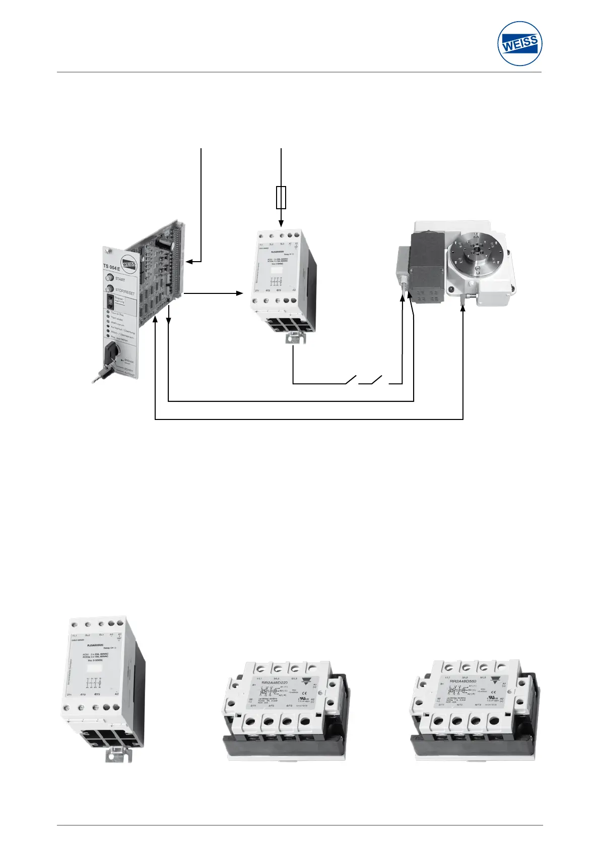
7.1 Circuit diagram
The motor line is switched by use of an electronic relay (solid state relay). Following this the two obligatory E-Stop
contactors must be connected to ensure a reliable shutdown in the event of an E-STOP.
Please see the motor name plate for the dimensioning of the motor protection switch. The motor line is a simple
non-screened line 4 x 1.5 mm².
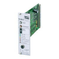
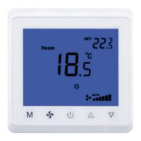
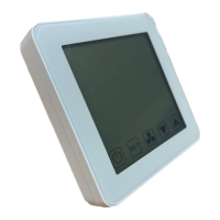
There are three versions of the “electrical contactor“:
7.2 Motor line
one direction
motor 0 ... 3kW
two directions of rotation
motor 0 ... 0,75kW
two directions of rotation
motor > 0,75kW
indexing table TC or TR
terminal C
E-STOP
brake
sensor
3 x 400V
motor line
terminal F
terminal D
24 V inputs and outputs
electronic
contactor