21
WT200MP Welding Machine
www.weldtech.net.nz
the parent metal. Draw the electrode slowly along
as it melts down.
Another diculty you may meet is the tendency, af-
ter the arc is struck, to withdraw the electrode so far
that the arc is broken again. A little practice will soon
remedy both of these faults.
20
o
1.6mm(1/16”)
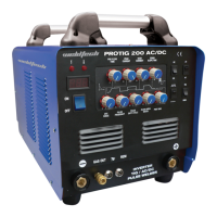
Striking an Arc
(Fig 1-20)
Arc Length
The securing of an arc length necessary to produce a
neat weld soon becomes almost automatic. You will
nd that a long arc produces more heat.
A very long arc produces a crackling or spluttering
noise and the weld metal comes across in large, ir-
regular blobs. The weld bead is attened and spatter
increases. A short arc is essential if a high quality weld
is to be obtained although if it is too short there is the
danger of it being blanketed by slag and the elec-
trode tip being solidied in. If this should happen,
give the electrode a quick twist back over the weld
todetachit.Contactor“touch-weld”electrodessuch
asE7014Stickelectrodesdonotstickinthisway,and
make welding much easier.
Rate of Travel
After the arc is struck, your next concern is to main-
tain it, and this requires moving the electrode tip
towards the molten pool at the same rate as it is
melting away. At the same time, the electrode has to
move along the plate to form a bead.
The electrode is directed at the weld pool at about
20º from the vertical. The rate of travel has to be ad-
justed so that a well-formed bead is produced.
If the travel is too fast, the bead will be narrow and
strung out and may even be broken up into individ-
ual globules. If the travel is too slow, the weld metal
piles up and the bead will be too large.
Making Welded Joints
Havingattainedsomeskillinthehandlingofanelec-
trode, you will be ready to go on to make up welded
joints.
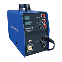
A. Butt Welds
Setuptwoplateswiththeiredgesparallel,asshown
in Figure 1-21, allowing 1.6mm to 2.4mm gap be-
tween them and tack weld at both ends. This is to
prevent contraction stresses from the cooling weld
metal pulling the plates out of alignment.
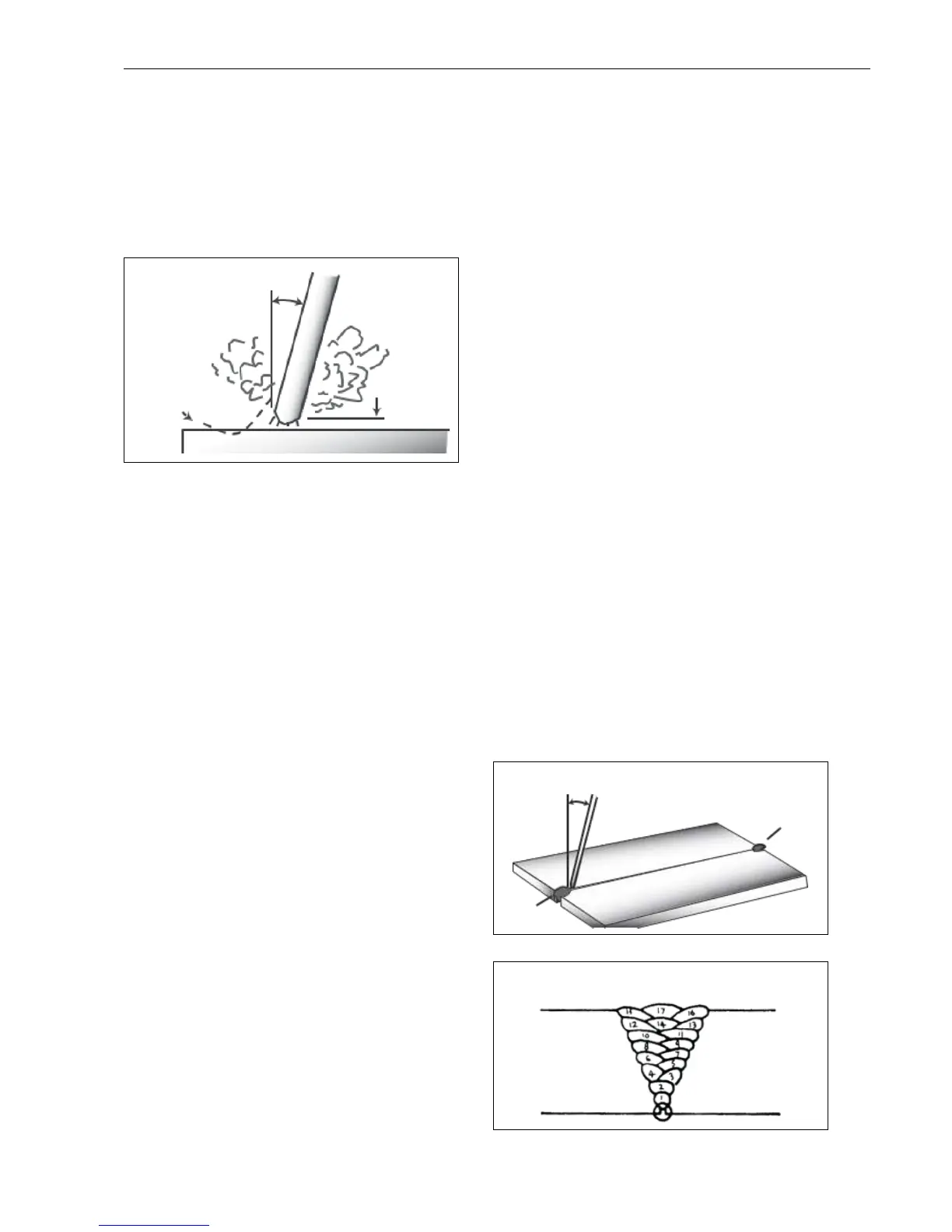
Plates thicker than 6.0mm should have their mating
edges bevelled to form a 70º to 90º included angle.
This allows full penetration of the weld metal to the
root. Using a 3.2mm E7014 Stick electrode at 100
amps, deposit a run of weld metal on the bottom of
the joint.
Do not weave the electrode, but maintain a steady
rate of travel along the joint sucient to produce a
well-formed bead. At rst you may notice a tendency
for undercut to form, but keeping the arc length
short, the angle of the electrode at about 20º from
vertical, and the rate of travel not too fast, will help
eliminate this.
The electrode needs to be moved along fast enough
to prevent the slag pool from getting ahead of the
arc. To complete the joint in thin plate, turn the job
over, clean the slag out of the back and deposit a
similar weld.
Tack Weld
Butt Weld
(Fig 1-21)
Electrode
20
o
- 30
o
Tack Weld
Weld Build Up Sequence
(Fig 1-22)
 Loading...