9
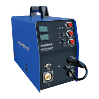
WT200MP Welding Machine
www.weldtech.net.nz
nect the earth clamp to the work piece. Contact
with the work piece must be rm contact with
clean, bare metal, with no corrosion, paint or scale
at the contact point.
5.2 Connect the MIG power connectionlead (14) to
the positive welding power output socket (12).
Note if this connection is not made, there will be
no electrical connection to the welding torch!
5.3 ConnectthespoolgunEuroConnectortotheMIG
torchEuro connection socket (1) on the front of
themachine.Securebyrmlyhandtighteningthe
threadedcollarontheMIGTorchconnectorclock-
wise. Connect the spool gun interface plug to the
spoolgunconnectionsocket(2).Setthespoolgun
switch(3)to‘on’position.
5.4 Connect the gas regulator to a gascylinder (not
includedwithmachine)andconnectthegashose
from the regulator to the gas inlet on the rear of
themachine(15).Ensureallhoseconnectionsare
tight. Open gas cylinder valve and adjust regulator,
owshould be between10-25 l/min depending
onapplication.Re-checkregulatorowpressure
with torch triggered as static gas ow setting may
drop once gas is owing.
5.5 Settheweldingvoltageadjustmentknob(8),wire
speed control knob (9) and inductance control
knob (10) to the desired positions.You are now
ready to weld!
7. Lift TIG Operation
NOTE: Lift TIG operation requires an optional valve control
TIG torch, and argon gas cylinder.
7.1 Connect the earth cable quick connector to the
positive welding power output socket (12). Con-
nect the earth clamp to the work piece. Contact
with the work piece must be rm contact with
clean, bare metal, with no corrosion, paint or scale
at the contact point.
7.2 InsertTIGtorchpowerconnectionintothenega-
tive welding power output socket (13). Connect
valveTIGtorchgaslinetotheregulator,ensuring
all connections are tight.
7.3 Open gas cylinder valve and adjust regulator, ow
shouldbebetween5-10l/mindependingonap-
plication. Re-check regulator ow pressure with
torch valve open as static gas ow setting may
drop once gas is owing.
7.4 Connectthemachinetosuitablemainspowerus-
ing the mains input power lead (16). Switch the
mains power switch (17) to‘on’to power up the
machine.Settheweldingmodeswitch(6)to‘Lift
TIG’.
7.5 Selecttherequiredoutputcurrentusingthecur-
rentcontrolknob(9).Youarenowreadytoweld!
NOTE: The WT200MP is a DC (Direct Current) output
welder only, this means that it is unable to TIG weld reactive
metals such as Aluminium alloys and Brass (which require
AC output). DC TIG output is suitable for steel, stainless steel
and copper. The New Model is the model in the range that
is designed for TIG welding Aluminium and its alloys.
Tips & Tricks
Duty Cycle Rating
Welding duty cycle is the percentage of actual weld-
ing time that can occur in a ten minute cycle. E.g.
20% at 160 amps - this means the welder can weld at
160 amps for 2 minutes and then the unit will need
to be rested for 8 minutes. All duty cycle ratings are
basedon an ambient air temperatureof 40°C with
50%humidity,whichistheinternationalstandardfor
such a rating. In an environment with temperature
s exceeding 40°C, the duty cycle will be less than
stated.Inambienttemperaturelessthan40°C,duty
cycle performance will be higher.
6. ARC/ MMA Welding Operation
6.1 Connect the earth cable quick connector to the
negativeweldingpoweroutputsocket(13) Con-
nect the earth clamp to the work piece. Contact
with the work piece must be rm contact with
clean, bare metal, with no corrosion, paint or scale
at the contact point.
6.2 Insert an electrode into the electrode holder and
connect the electrode holder and work lead to the
positiveweldingpoweroutputsocket(12).
NOTE: This polarity connection conguration is valid for
most GP (General Purpose) MMA electrodes. There are vari-
ances to this. If in doubt, check the electrode specications
or consult the electrode manufacturer.
6.3 Connect the machine to suitable mains power us-
ing the mains input power lead (16). Switch the
mains power switch (17) to‘on’to power up the
machine.Settheweldingmodeswitch(6)to‘ARC’.
6.4 Selecttherequiredoutputcurrentusingthecur-
rentcontrolknob(9).Youarenowreadytoweld!
 Loading...