7
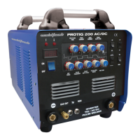
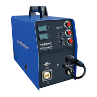
WT200MP Welding Machine
www.weldtech.net.nz
Basic Operation - MIG Welding
1. Fitting Wire Spool
1.1 Openthewirefeedercompartmentdoor.Remove
thewirespoolholder(18)bythreadingitanticlock-
wise.Ifusing5kg/D.200spool,checkthatthe5kg
spoolspacersleeveisttedtothespoolholder.Fit
the wire spool to spool holder, ensuring that the
wire exits the spool towards the wire feeder from
bottom the spool.
1.2 To replace the spool holder, set the spool brake
tension by adjusting the spool tension adjust-
ment hex screw in the middle of the spool holder.
Clockwise to increase spool brake tension and an-
ti-clockwise to decrease. The spool brake tension
should be set so that the spool can rotate freely,
but does not continue to rotate once the wire feed
stops. This may need to be adjusted as the wire is
used up and the spool weight decreases.
WARNING!
Excessive spool brake tension will cause wire feeding
issues and aect welding performance as well as
premature failure/ wear of wire feed components.
Insucient brake tension will cause the spool to
‘freewheel’ and the welding wire will unravel from
the spool (known as a ‘birds nest’)
1.3 Feed the wire from the spool through the wire
driveinletguide(19)intothewirefeeder.
2. Loading Wire Feeder
2.1 Release the wire feed tension arm (21) by pivot-
ingthewirefeedtensionadjustmentlever(20)to-
wards you from the vertical ‘locked’ position.
2.2 Checkthewiredriveroller(23)groovematchesthe
selectedMIGwiretypeandsize.Thedriverollerwill
have two dierent sized grooves; the size of the
groove in use is stamped on the side of the drive
roller.Foruxcored‘soft’wire,suchasthatusedin
gaslessMIGwelding,thedriverollergroovehasa
serratedprole(knownasknurled).Forsolidcore
‘hard’MIGwire,thedriverollergrooveusedhasa
‘v’ shaped prole. For Aluminum solid core‘soft’
MIGwire,thedriverollerrequiredhasa‘u’shaped
groove. If necessary, remove and change the drive
rollerbyunthreadingthedriverollerretainer(22).
Once the correct drive roller (23) isselected and
tted and the driveroller retainer (22) issecured
in place, manually feed the wire through the wire
drive inlet guide (19), through the drive roller
groove and into the outlet wire guide tube. En-
suring that the wire is correctly seated in the drive
roller groove, replace the wire feed tension arm
(21)andlockitintoplacebypivotingthewirefeed
tensionadjustmentlever(20)backtothevertical
position.
2.3 Adjusting wire feed tension. This is accomplished
by winding the knob on the tension adjustment
lever (20). Clockwise will increase tension, anti-
clockwise will decrease drive tension. Ideal tension
is as little as possible, while maintaining a consist-
ent wire feed with no drive roller slippage.
2.4 Check all other causes of excess wire feeding fric-
tioncausingslippagerst,suchas;incorrect/worn
drive roller, worn/ damaged torch consumables,
blocked/ damaged torchwire guide liner, before
increasing wire feed tension. There is a number
scaleonthetensionadjustmentlever(20)toindi-
cate the adjustment position. The higher the num-
ber indicated, the higher the tension that is set.
WARNING!
Before changing the feed roller or wire spool, ensure
that the mains power is switched o.
WARNING!
The use of excessive feed tension will cause rapid
and premature wear of the drive roller, the support
bearing and the drive motor/ gearbox.
2.5 ConnecttheMIGTorchEuroConnectortotheMIG
torchEuro connection socket (1) on the front of
themachine.Securebyrmlyhandtighteningthe
threadedcollarontheMIGTorchconnectorclock-
wise.
2.6 Check that the correct matchingMIG wire, drive
roller(23)andMIGtorchtiparetted.
2.7 Connect the machine to suitable mains power us-
ing the mains input power lead (16). Switch the
mains power switch (17) to‘on’to power up the
machine.Settheweldingmodeswitch(6)to‘MIG’
position.
2.8 You are now ready to feed the wire through the
torch. With the wire feeder cover open, pull the
triggeroftheMIGtorchtocheckthatthewireis
feeding smoothly through the feeder and into the
torch.
2.9 Setthewirefeedingspeedknob(9)tomaximum.
With the torch tip removed from the torch and the
torchlaidoutasstraightaspossible,depressMIG
torch trigger until the wire feeds out through the
 Loading...