ASSEMBLY AND ADJUSTMENTS
12
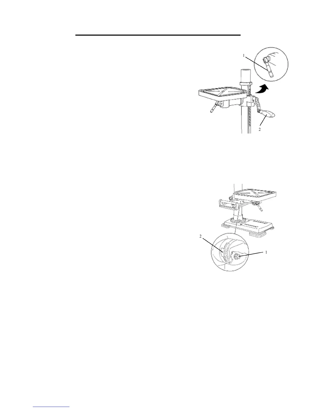
RAISE OR LOWER THE TABLE (Fig. 11)
1. Loosen the support lock handle (1) and turn the crank handle (2) until
the table is at the desired height.
2. Tighten the support lock handle before drilling.
ROTATE THE TABLE (Fig. 11)
1. Loosen the support lock handle (1) and turn the table around the
column to the desired position.
Note: The rack should rotate around the column with the table support
bracket. If the rack binds and does not rotate, slightly loosen the set
screw in the rack collar.
2. Tighten the support lock before drilling.
TILT THE TABLE (Fig. 12)
1. Rotate the table clockwise with the fork wrench. Pull out the location
pin. Put the location pin and nut in a suitable area.
2. Rotate the bolt (1) counterclockwise with a wrench to loosen it.
3. Adjust the angle of the table.
4. Tighten the bolt with fork wrench.
ADJUST THE TABLE TO BE HORIZONTAL
1. Rotate the bolt (1) counterclockwise with a wrench to loosen it.
2. Rotate the table to 0˚.
3. Hit the location pin (2) into the location hole in the table support with a hammer.
4. Tighten the nut of the location pin (2) slightly.
5. Lock the bolt (1) with a wrench.
Fig. 11
Fig. 12
 Loading...