88
ASSEMBLY
ASSEMBLY
WARNING: To avoid injury from accidental startups, turn switch OFF and remove the plug from the power
source outlet before making any adjustments.
NOTE: The table insert is only to be used with the sanding drums, not with the sanding belt attachment.
Place the spindle nut, table inserts, sanding drums, sanding sleeves, spindle washers, belt-sanding attachment and
spindle nut wrench in the appropriate storage slots beneath the table (Fig. A & Fig. B). A sanding drum does not
need to be installed until after the initial test startup. For drum and belt installation instructions, see p. 10.
Fig. A
Fig. B
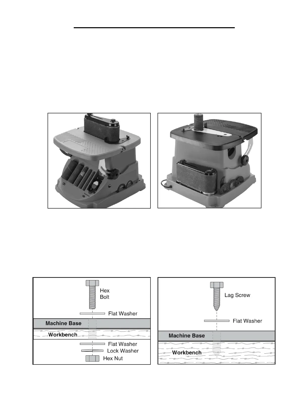
MOUNTING THE UNIT
The base of this machine has four 1/4 inch mounting holes on the corners of the base. Mount to a benchtop sur-
face to maximize safety and minimize vibration, walking, tipping and wobbling.
The strongest mounting option is a through mount, where the bolts go all the way through the work surface (Fig.
C). The other option is a direct mount, where the sander is mounted using screws that go directly into the work
surface (Fig. D).
Fig. C
Fig. D