WARNING: To prevent serious injury from accidental operation, make sure the power cord is discon-
nected from the power source and the tool is switch to OFF before assembly or making any adjustments.
12
ASSEMBLY
Unpacking
• Remove all packaging materials.
• Remove remaining packing and package inserts (if included).
• Check that the package contents are complete.
• Check the appliance, the power cord, the power plug and all accessories for
transportation damage.
• Keep the packing materials as long as possible until the end of the warranty
period.
WARNING
Packaging materials are not toys! Children must not play with plastic bags!
Danger of suffocation!
INSTALLATION OF RUBBER
FEET (Fig. 1)
• Insert the rubber feet into the
4 holes in the base (fig. 1).
INSTALLATION OF THE
DIAMOND DISC AND METAL
BRACKET (Fig. 2-12)
• Unplug the tile saw from the mains
supply.
• Remove the cover (45º vertical
fence) of the water tank (fig. 2).
• Remove the fixing screw & washer
of the blade guard (fig. 3).
• Swing the blade guard then lift it
out of the notch (fig. 4-5).
• Remove the nut and outer flange
from the spindle (fig. 6).
• Fit the diamond disc (fig. 7). Please
pay attention to the rotation
direction on the diamond disc. The
direction arrows on the disc must
be in the same direction as that
marked on housing.
• Ensure the diamond disc is fully
located and centred.
fig.7
fig.1 fig.2
fig.3 fig.4
fig.5 fig.6
fig.8
ASSEMBLY
9
12
ASSEMBLY
Unpacking
• Remove all packaging materials.
• Remove remaining packing and package inserts (if included).
• Check that the package contents are complete.
• Check the appliance, the power cord, the power plug and all accessories for
transportation damage.
• Keep the packing materials as long as possible until the end of the warranty
period.
WARNING
Packaging materials are not toys! Children must not play with plastic bags!
Danger of suffocation!
INSTALLATION OF RUBBER
FEET (Fig. 1)
• Insert the rubber feet into the
4 holes in the base (fig. 1).
INSTALLATION OF THE
DIAMOND DISC AND METAL
BRACKET (Fig. 2-12)
• Unplug the tile saw from the mains
supply.
• Remove the cover (45º vertical
fence) of the water tank (fig. 2).
• Remove the fixing screw & washer
of the blade guard (fig. 3).
• Swing the blade guard then lift it
out of the notch (fig. 4-5).
• Remove the nut and outer flange
from the spindle (fig. 6).
• Fit the diamond disc (fig. 7). Please
pay attention to the rotation
direction on the diamond disc. The
direction arrows on the disc must
be in the same direction as that
marked on housing.
• Ensure the diamond disc is fully
located and centred.
fig.7
fig.1 fig.2
fig.3 fig.4
fig.5 fig.6
fig.8
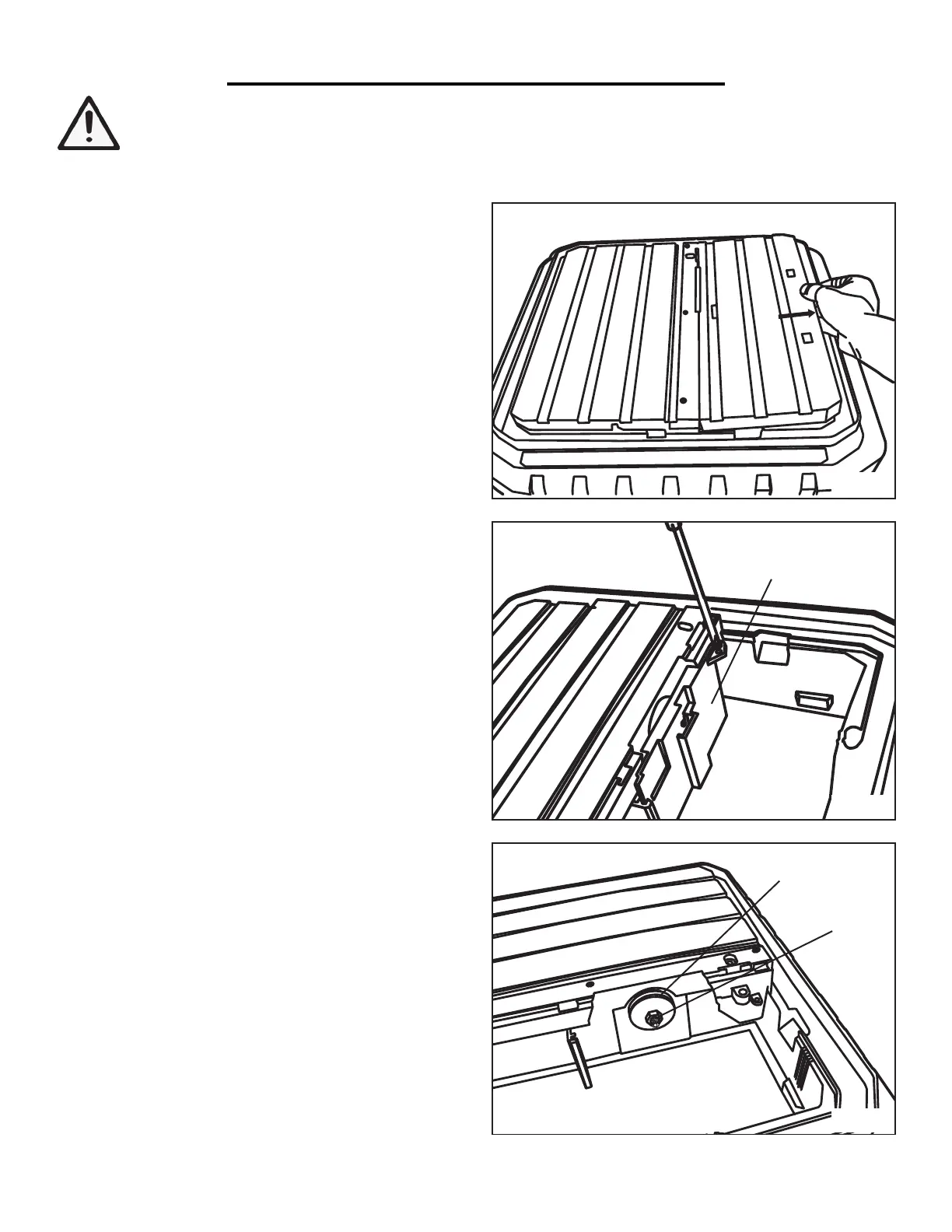
Fig. D
Fig. E
Lower Blade Guard
Outer Flange
Nut
Fig. F
INSTALLING THE DIAMOND DISC AND METAL BRACKET (Fig. D to L)
1. Remove the 45° bevel table to access the lower blade
guard inside the water tank (Fig. D).
2. Loosen and remove the screw and washer from the
lower blade guard (Fig. E). Swing the lower blade guard
open and lift it out of the notch.
3. Remove the nut and outer flange from the spindle
using the two included wrenches (Fig. F). Do not re-
move the inner flange.
(Continued on next page)

 Loading...