6
|
English
1. ASSEMBLE AND INSTALL STRAP MOUNT
Fig. 1.1
Fig. 1.2
1
2
3
Frame Rod Holes
Easy Removal
Slots
Prongs
with
Pivot
Pins
Slotted
Receiver
4
Gator
Grommet™
Extender
Arm
Angle Brace
Kevlar
Strap
Ratchet Handle
Release
Lever
Center
Slot
Grommet Pins
(top and bottom)
Installation Slot
(top and bottom)
Adjustment
Teeth
(top and bottom)
Center
Section
Strap
Guides
Thick Side
Thin Side
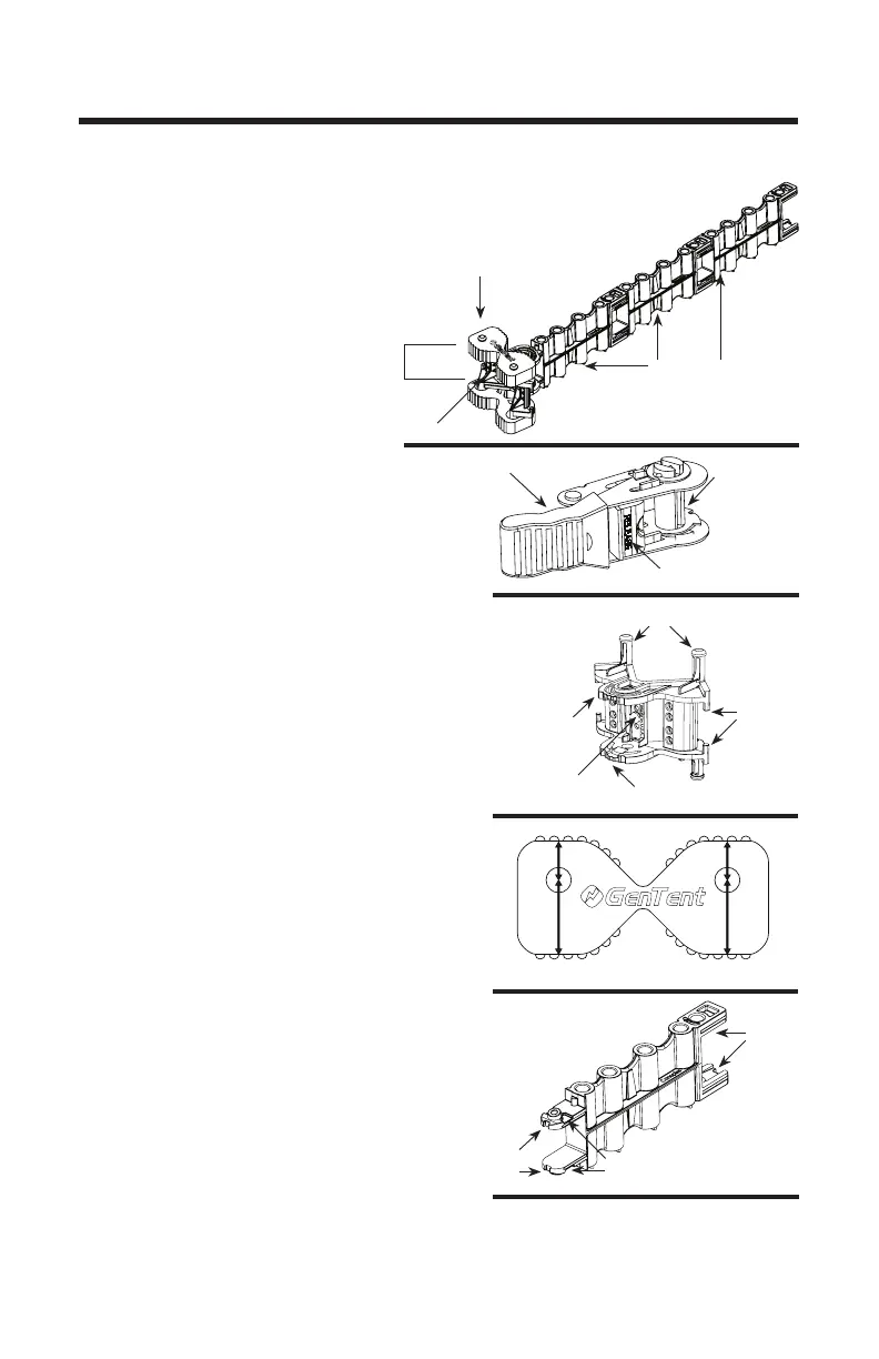
Understanding the Mounting
Components
The Angle Braces and Extender
Arms work together with the
Kevlar
®
ratchet buckle (Fig. 1.1)
to create a stable and strong
mounting point for the GenTent
frame on your inverter generator.
The Kevlar
®
Ratchet Strap (Fig.
1.2) is installed through the Angle
Brace center and is tightened to create the
base of the mounting assembly to your
inverter case.
The Angle Braces (Fig. 1.3) are held to the
four corners of your case along with the
Gator Grommets™ by the Kevlar
®
Ratchet
Strap and creates a rm mounting and
adjustment point for the Extender Arms.
The Gator Grommets™ (Fig. 1.4) are
pressed onto the pins of the Angle Brace
to create a corner mounting assembly.
The grommets allow the assembly to grip
the generator case without marring the
surface. Each Gator Grommet™ has two
(2) thicknesses allowing for optimal t on
various case shapes.
The Extender Arms (Fig. 1.5) will con-
nect directly to the corner Angle Brace.
Additional Extender Arms can be added
to provide additional support for the Gen-
Tent frame.
Fig. 1.3
Fig. 1.4
Fig. 1.5
ASSEMBLY