Page 3-9
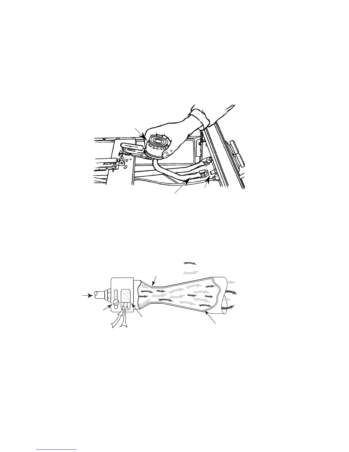
= Gas
= Air
Venturi
(Constricting
Area)
Adjustment
Screw
Adjustable
Air Shutter
Expanding
Area
Primary Air
Gas Inlet
Mixed Air &
Gas Outlet
Figure 3-12
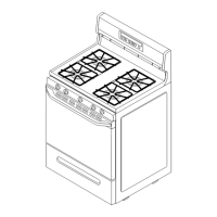
The
Cooktop Burner Assembly
controls the combustion of gas and directs its flame (see Figure
3-11). Burners are manufactured from galvanized steel and have common component parts:
1. An
Air Shutter
to control the amount of primary air to be mixed with the gas.
2. A
Venturi
to provide a pathway for gas to flow to the burner from the orifice. Air enters the
burner through the venturi tube, and is used as a pathway for gas, as well as an area for gas
and air to be mixed together for combustion.
3. A
Burner Head
to provide an exit for gas so it can be ignited. The exits are normally holes,
or slots, called “burner ports.”
Figure 3-11
Venturi
Burner Head
Air Shutter
AIR SHUTTER & VENTURI
An inlet for primary air is provided before the gas supply reaches the burner port. This inlet is called
an “air shutter” (see Figure 3-12). The air shutter is adjustable to allow a better adjustment of the
air-gas mixture needed for combustion, and results in more efficient combustion.