PAGE 12
FOR SERVICE TECHNICIAN’S USE ONLY
DO NOT REMOVE OR DESTROY
TROUBLESHOOTING TESTS
TEST #1: Main Control
This test checks for incoming and outgoing supplies to and
from the main control. This test assumes that proper voltage
is present at the outlet.
1. Unplug washer or disconnect power.
2. Remove console to access main control.
3. Verify that ALL connectors are inserted all the way into the
main control.
4. Plug in washer or reconnect power.
5. With a voltmeter set to AC, connect black probe to J7-3
(Neutral) and red probe to J7-1 (L1).
J2-5 OPEN
J2-4 BLK +13VDC
J2-3 GRY -5VDC (CIRCUIT GND)
J2-2 PNK RPM INPUT
J2-1 BLU SHIFTER POSITION INPUT
J3-10 BLK TEMP THERMISTOR INPUT (HYBRID)
J3-9 BLK TEMP THERMISTOR GND (HYBRID)
J3-8 OPEN
J3-7 OPEN
J3-6 OPEN
J3-5 BLU COLD VALVE (L1)
J3-4 RED HOT VALVE (L1)
J3-3 OPEN
J3-2 OPEN
J3-1 WHT NEUTRAL
J4-3 BLU PRESSURE TRANSDUCER INPUT
J4-2 OPEN
J4-1 BLU -5VDC (CIRCUIT GND)
J7-3 BLK NEUTRAL
J7-2 GRN CHASSIS GROUND
J7-1 BLK L1
J2
J3
J7
J4
J10
J11
J16
J15
SHIFTER VALVES TEMP
POWER
CORD
PRESSURE
TRANSDUCER
ROTARY ENCODERSROTARY ENCODERS
LID LOCK
DRAIN MOTOR
J10-6 BLK ROW 2
J10-5 BLK ROW 3
J10-4 BLK COLUMN 0
J10-3 BLK COLUMN 1
J10-2 BLK COLUMN 2
J10-1 BLK COLUMN 3
J11-6 RED ROW 4
J11-5 RED ROW 5
J11-4 RED COLUMN 0
J11-3 RED COLUMN 1
J11-2 RED COLUMN 2
J11-1 RED COLUMN 3
J15-4 RED LOCK SWITCH
J15-3 WHT NEUTRAL
J15-2 BLU LID SWITCH INPUT
J15-1 YEL LOCK SWITCH SOLENOID (L1)
J16-7 ORN MOTOR CCW WINDING (L1)
J16-6 RED MOTOR CW WINDING (L1)
J16-5 OPEN
J16-4 WHT MOTOR (NEUTRAL)
J16-3 LT BLU DRAIN PUMP MOTOR (L1)
J16-2 W/ BLU SHIFTER MOTOR (NEUTRAL)
J16-1 BRN SHIFTER MOTOR (L1)
If 120VAC is present, go to step 6.
If 120VAC is not present, check the AC power cord
for continuity (See Figure 9).
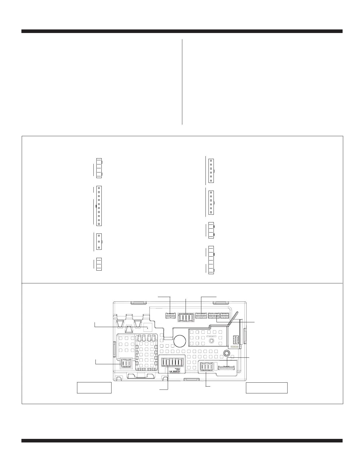
6. Is the “Diagnostic LED” ON or OFF? (See Figure 3 below
for LED location.)
ON: (+5VDC present) continue to step 7.
OFF: (+5VDC missing) proceed to step 8.
7. With a voltmeter set to DC, connect black probe to J2-3
(Circuit Gnd) and red probe to J2-4 (+13VDC).
If +13VDC is present, main control supplies are good.
If +13VDC is not present, go to step 8.
Diagnostic
LED
J7-Power
Cord
J16-PSC Motor/Drain
J15-Lid Lock
J3-Temperature
Sensor/Valves
= represents pin-1
J10-Rotary
Encoders
* Not available on all models
J7
J2
J4
J3
J16
J15
J11
J10
Main Control Board Connectors & Pinouts (Figure 3)