For Service Technician Use Only
COMPONENT TESTING
Whirlpool
®
Smart Wall Ovens
n
3-13
Component Testing
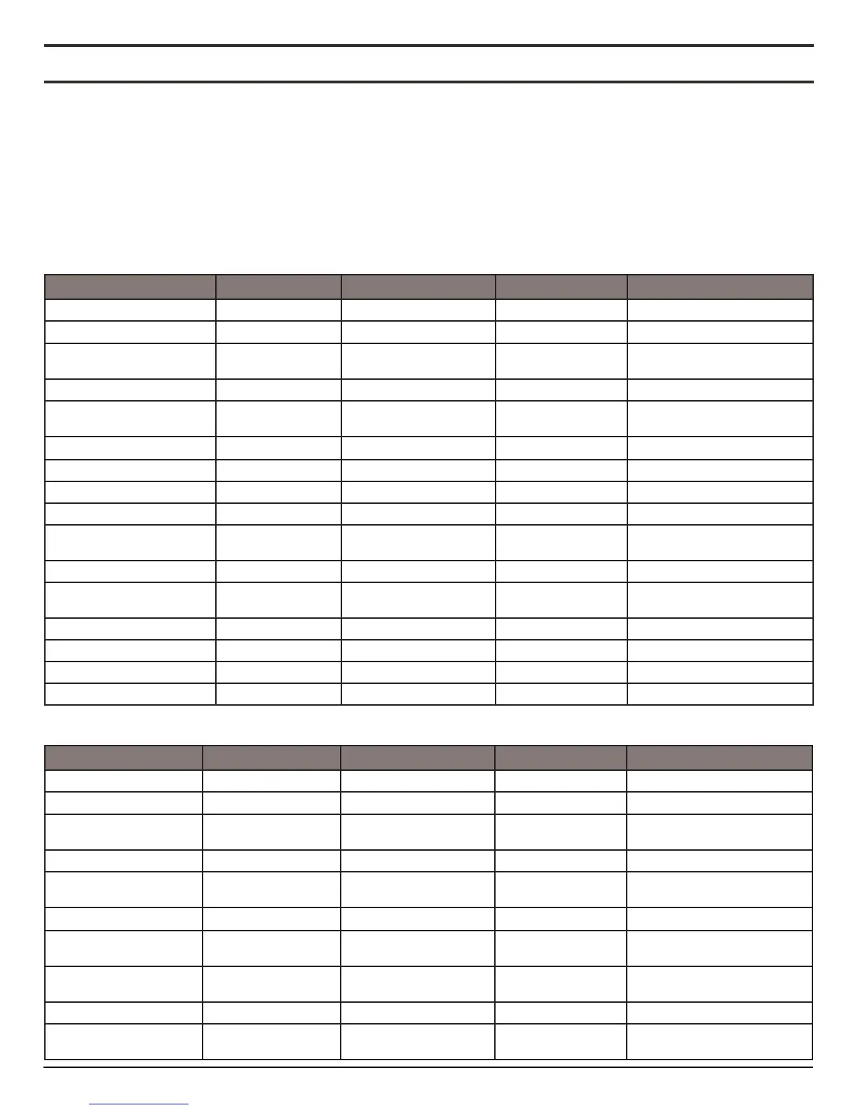
The following charts provide pin locaons and Voltage/Resistance values for all components used in the oven and microwave. These
charts should be used to conrm that a component is operang properly. All this tesng informaon is also available in the Tech Sheet
that is provided with every oven Whirlpool produces.
To properly check for voltage, complete the following steps:
1. Unplug the oven or disconnect power.
2. Connect voltage measurement equipment to check points.
3. Plug in the oven or reconnect power and conrm voltage
reading.
4. Unplug the oven or disconnect power.
Component Serviceable Side Check Points Copernicus
Lights Front P7-1 to L1 (J8-1) 0 Ω to 40 Ω 120 VAC
Latch Switch Front P3-7 to P3-5 Open circuit
Door Switch Front P3-6 to P3-5 Closed circuit with
oven door closed
Latch Motor Front P5-1 to N (J8-2) 500 Ω to 3000 Ω 120 VAC motor running
Oven Temperature Sensor Front P3-1 to P3-2 1075 Ω at 68°F
(20°C) DLB
Meat Probe Side P3-3 to P3-4 9876-10075 Ω
Blower Motor—High Speed Rear P5-5 to N (J8-2) 15 Ω to 23 Ω 120 VAC motor running
Blower Motor—Low Speed Rear P5-4 to N (J8-2) 15 Ω to 23 Ω 120 VAC motor running
Thermal Limiter Rear PX3-1 to L2 (Main line) Closed circuit 0 V closed, N/A open
Thermal Fuse (only for
single/double)
Front PX1-1 to PX3-2 Closed circuit 0 V closed, N/A open
Convecon Fan Rear P5-3 to N (J8-2) 20 Ω to 28 Ω 120 VAC motor running
Convecon Element Front PX1-3 to PX3-2 21.3 Ω to 24.7 Ω 240 VAC Convecon cycle
operang
Bake Element Rear PX1-1 to PX3-2 19.0 Ω to 21.6 Ω 240 VAC Bake cycle operang
Broil Element Front PX4-2 to PX3-2 14.8 Ω to17.2 Ω 240 VAC Broil cycle operang
User Interface Board Front P1-4 to P1-1 N/A 14 VDC
Copernicus ACU Side (Combo) P1-2 to P1-5 N/A 14 VDC
Component Serviceable Side Check Points Copernicus
Lights Front P7-1 to L1 (J8-1) 0 Ω to 40 Ω 120 VAC
Latch Switch Front P3-7 to P3-5 Open circuit
Door Switch Front P3-6 to P3-5 Closed circuit with
oven door closed
Latch Motor Front P5-1 to N (J8-2) 500Ω to 3000Ω 120 VAC motor running
Oven Temperature
Sensor
Front P3-1 to P3-2 1075Ω at 68°F (20°C)
DLB
Meat Probe Side P3-3 to P3-4 9876-10075 Ω
Cooling Fan Motor —
High Speed
Rear P5-5 to N (J8-2) 15 Ω to 23 Ω 120 VAC motor running
Cooling Fan Motor —
Low Speed
Rear P5-4 to N (J8-2) 15 Ω to 23 Ω 120 VAC motor running
Thermal Limiter Rear PX3-1 to L2 (Main line) Closed circuit 0 V closed, N/A open
Thermal Fuse (only for
single/double)
Front PX1-1 to PX3-2 Closed circuit 0 V closed, N/A open