_ •
.,,.
,,
,_,._
...
U:t
'
............
'W
..........
OUlU
t..17
hand so that
point
A is moved to point
B when
readi~
the
indicator
.
Any
deviation in
angularity
between the
saw blade and the direction
of
feed
should
be maintained within the
rnachine manufacturer's recommen-
dations
. On
double
cut-off
and panel
trim machines
any
slight
angularity in
aiiQnment should
be
controlled so that
the trailing edge
of
the saw blades do
nor re-cut the material.
4. WITH ALL
MACHINE
POWER OFF
AND LOCKED
OUT,
inspect the saw
bMlde before
mounting
. The bore
(center hole) must
be
the correct size
and fit snugly.
Do
not
force a saw
or
other
type of
too
l on an arbor.
Do
not
tighten
mounting
screws uneQually, or
use Incorrectly fitted keys.
Incorrect
mounting
of saws or other tools can
cause tool breakage and create
dangerous operating
conditions
.
Never mount a saw blade
with
a
damaged (deeply scored or
out
of
roun.d) bore
or
arbor
. Inspect the teeth
carefully
. Do
not
mount
blades with
damge'd-bodies
, dull
or
damaged
(bent
or
chipped) teeth. Never use
11nything other than accurate metal
shim&.
or
spacers
if
saw blades have to
be positioned
on
the arbor. Never use
shims
to
"wobble"
a saw blade.' Be
sure that
all
saw collars used match
exactly
in
diameter. Closely
check
to
see that the arbor
nut
threads are
not
worn
and
the
wrench
surfaces
of
the
arbor
nut
are
not
rounded
off
.
5.
WITH
ALL
MACHINE
POWER OFF
AND
LOCKED
OUT,
mount the saw
blade on the
arbor
making sure that
the saw blade is
turning
in the correct
r
otation
and that the arbor
nut
tightens
in a
directivn
opposite
to the blade
rotation (See Fig. 4A
& 48). Unless the
Fig. 4A
~-
f'FYv:::._
=-"-~~--JM
DI'~
....
~
)
.y-
~-~-
~
'-==--
·
-c
__
c_----==--s!•lD
fOQ.llDT•'ffa.DotiMT..-cTIQllor...C
Fig.
48
nachine
is specifically designed for
;uch
cutting;never
mount
saw
nachine
tools to
"climb
cut"
(teeth
:utting
in
the same
direction
of
feed)
>n
manually
led machines.
Never
use
aw blades on
operations
for
which
hey were not designed;
for
example,
!o
nol
.use
rip
design blades
to
cut
cross the grain,
etc
.
;tRCULAR SAW BLADES AND
:.AW
MACHINE
TOOLS
:TART•UP,PROCEDURES
.
TURN
OFF
M•D
LOCK
OUT
ALL
tACHINE
POWER. Never assume
reviously
set
machine
or
tool
onditions
to
be
correct. Be
sure
that
3.
Mounting
.a
.saw blade
to
"wobble"
means to
shim
the blade
body
un-
equ
.ally on
one
side,
throwing
the
saw
~~t
of
alignment
with
the
arbor.
This
causes the saw to
make
a wider
cul
and
dangerously
increases
pressures
on
the tool.
1oc~eo
on ine
arbor
(See Fig. 4A &
46)
,
turns freely (no
foreign
objects in tool
rotation path)
and
is
properly
positioned for the
cutting
operation
reQuired
(See
Fig.
3)
. Check to see
that the cutti
ng
tool
is
not dull
or
damaged. '::"leek to see that the body
of
the saw blade is
not
cracked.' Take
special precaution to check "stacked
cutters" to
be sure that all bolts. pins
and threaded parts are
no
t worn
or
damaged, and are
proper
ly
mounted.
Be sure that hubs on al!
"split"
circular
tools are properly fitted and pinned
and that the
locking
collars are in
place and lit
properly
. Do not use
locking collars that are not matched to
the "split tool." Split collars on split
tools are not recommended.
2. WITH ALL
MACHINE
POWER OFF
ANO LOCKED
OUT
insure that you
are not attempling
to
operate tools that
do not
conform
to
the machine
manufacturer's
machine
load
specifications in either size or weight,
or
that
do
not
mount
according to the
machine design limitations. Operate
saw machine toots
only
on the type
of
materials,
cutting
loads and operation
applications for
which
the tools were
designed
(II
you
don
't
know
this
information. ask
your
supervisor.) Do
not
operate saw blades
or
saw
machine tools in excess
of
the
machine or tool
manufacturer
's
specifications,
or
current
applicable
OSHA standards,
or
in
excess
of
18,000 sfm (surface feet per
minute).'
(See Charts A and B
following)
.
3. WITH ALL
MACHINE
POWER OFF
ANO LOCKED
OUT
position
the
cutting
tool, material guides and
material
hold-downs
so that the
material
to
be
cut
is fully
supported
.
This will insure there will be
minimal
material vibration. Next,
follow
the
machine manufacturer's
instructions
to
mount
all guards over the toots such
that the guards are close to.
but
properly
clear. the material being cut.
Mount
and activate all
of
the machine
safety devices such
as
anti-kickback
mechanisms, spreaders.
dust
hoods
and safety switches. Make sure all
personnel and all
loose
or
foreign
objects are clear
of
the
machine
and
cutting
tools.
4. TURN ON
MACHINE
POWER, start
the tool rotation
slowly
before feeding
material. This is
done
by
"jogging"
(that is, pressing the start
button
and
immediately after that pressing
the
stop button). At a safe distance.
observe the operating
condition
of
the
tools (by sight and sound)
as
they
rotate
slowly
. Next.
TURN
ALL
MACHINE
POWER OFF AND
LOCKED
OUT, wait
LJntil
all
cutting
tools stop rotating
by
themselves (do
not
attempt to
stop
their
rotation
yourself unless
a brake is specifically
provided for that
purpose
on
the
machine), and make any necessary
COl'rections.
Go
through
a111teps
noted
in
paragraph 3,
just
above,
before
you
TURN THE
MACHINE
POWER
ON
. Press the start
button
and allow the machine to operate at
4.
"All
cracked saws shall be removed
from service
,"
Department
of
Labor
OSHA Standards, Federal Register
29
CFR Part 1910.213(5) (7) .
5. The term "surface feet per
minute"
refers
to
the peripheral or rim speed
of a
cutting
tool. See
"Operating
Speeds for
Carbide
Tipped' Rotary
Cuttir;ig
Tools
" below.
before feeding material.
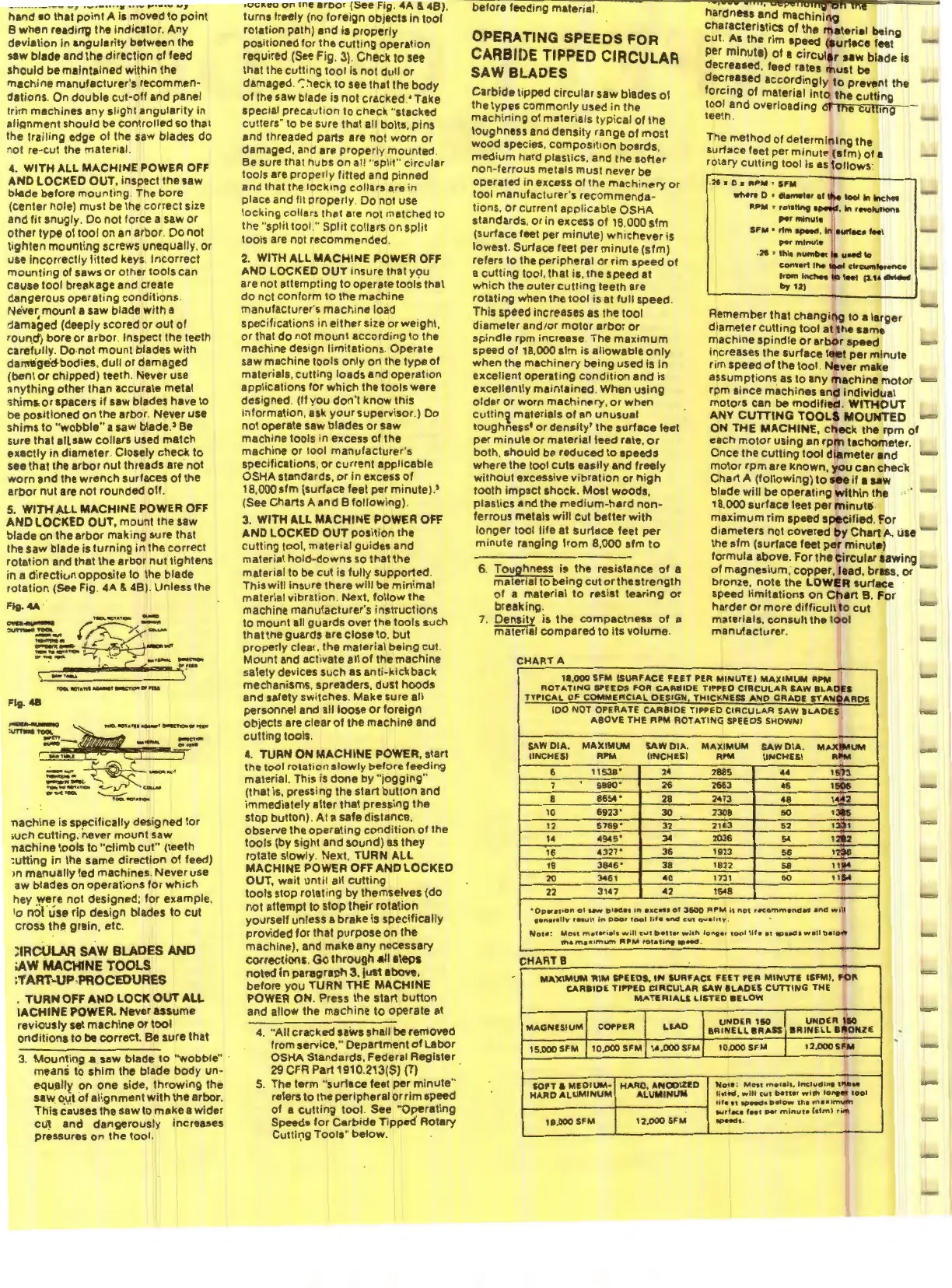
OPERATING
SPEEDS
FOR
CARBll>E
TIPPED
CIRCULAR
SAW BLADES
Carbide tipped
circular
saw blades
of
the types
commonly
used in the
machining
of materials
ty
pica
l of
the
toughness and density range of
most
wood species, composit
ion
boards
medium hard plastics. and the
sof1~r
non-ferrous metals must never be
operated in excess
of
the
machinery
or
tool manufacturer's
recommenda-
tions,
or
current applicable
OSHA
standards, or in excess
of
16.000
slm
(surface feet per
minute)
whichever
is
lowest. Surface feet per
minute
(sfm)
refers to the peripheral
or
rim speed
of
a
cutting
tool, that is. the speed at
wh
ich the outer
cutting
teeth are
rotating when the
tool
is at full speed.
This speed increases
as the
tool
diameter and/
or
motor
arbor
or
spindle rpm increase. The
maximum
speed
of
18,000
slm
is allowable
only
when the
machinery
being used
is
in
excellent operating
condition
and is
excellently maintained. When
using
older
or
worn machinery,
or
when
cuttin!i
materials
of
an
unusual
toughness• or
density'
the
surface
feet
per
minute
or
material feed rate,
or
both. should
be
reduced
to
speeds
where the tool cuts easily and freely
without
excessive
vibration
or
high
tooth
impact
shock
. Most woods,
plastics and the
medium-hard
non-
ferrous metals
will
cut
better
with
longer
tool life at surface feet
per
minute
ranging
from
8,
000
sfm
to
6. Toughness is
the
resistance
of
a
material to
being
cut
or
the
strength
of
a material
to
resist
tearing
or
breaking.
7. Density is the
compactness
of
a
material
compared
to its
volume
.
CHART
A
ha~dness
a'nd
machini
ng
characteristics
of
the
ma
terial being
cut
.
A~
the rim speed (aur1ace feet
per
minute)
of
a
circul
ar
uw
blade is
decreased, feed rates
must
be
dec~eased
accordingly
to
prevent the
forcing
of
material
Into
the
cutting
tool and overloading of the
cutting
teeth.
The
method
of determin
ing
the
surface feet per
minute
(Sim)
of
1
rotary
cutting
tool is
as
fo
llows:
.
26
• 0 a
"PW
•
SFM
_,.
D • ctl•metor ot
U..
lool
In
lnchn
RPM
1:
rot•tlng
aprlll9Cf
,
k\
'"Otutk)n1
,..,
""""'•
SFM •
r1m
ap.M
,
In
aur1ace f
..
t
pe-t
minute
.
2'
• Ihle numl>Of
11
uMCI
lo
conYert
thit
tool
cltcumfefence
from
fnchea
lo
tfft
(1.
tt
...-...
by
121
Remember that
changi
ng
to a
larger
diameter
cutting
tool
at
the
same
machine spindle
or
arb
or speed
increases the surface f
eet
per
minute
rim speed
of
the tool.
Never
make
assumptions
as
to
any
ma
chine
motor
rpm since machines and
individua
l
motors
can
be
modified.
WITHOUT
ANY
CUTTING
TOOLS
MOUNTED
ON
THE
MACHINE,
check
the
rpm
ol
each
motor
using
an
rp
m tachometer.
Once
the
cutting
tool
diameter
and
motor
rpm are
known.
you
can
chec
'k
Chart
A
(following)
to
see if a saw
blade
will
be
operating
w
ithin
the
18,000 surface feet
per
mi
nute
.
maximum
rim speed
specified
. For
diameters
not
covered
by
Chart
A, use
the sfm (surface feet
pe
r
minute)
formula above.
For
the
c
ircular
sawing
of
magnesium;
copper, lead, brass,
or
bronze.
note
the LOW
ER
surface
speed
limitations
on
Chart
B.
For
harder
or
more
difficult
to
cut
materials,
consult
the t
oo
l
manufacturer
.
11,000
SFM
!SURFACE
FEET
PER
MINUTE!
MAXIMUM
RPM
ROTATING
6PEEDS FOR
CARBIDE
TIPPEO
CIRCULAR
SAW
BLA
DES
TYPICAL
OF
COMMERCIAL
OESIGN
,
THICKNESS
AND
GRADE
STAN
OAR
OS
100
NOT
OPERATE
CARBIOE
TIPPEO
CIRCULAR
SAW
BLADES
ABOVE
THE
RPM
ROTATING
SPEEDS SHOWN)
SAW
OIA.
MAXIMUM
SAW
DIA.
MAXIMUM
SAW
DIA
.
MAXIMUM
UNCHESI RPM
UNCH
ES) RPM
UNCHESI
Rl'M
6
11538'
24
2885
44
1573
7
9590·
26
2663
I
46
1506
8
8654·
28
2473
48
1
442
10
6923.
30
2308
50
1315
12
5769'
32
2163
52
1331
14
4945•
34
2036
54
1212
16
4327•
36
1923
!>6
n36
18
3945•
38
1822
58
11
94
20
3461
40
1731
60
115"4
22
3147
42
1648
•Operation
ot
uw
bl•d••
in
exc:ns
ot
3600
"PM
is
not
,•commended
and
will
t•"H•
l
ly
'"""
It
in
poor
tool
life
•nd
cvt
Quallt¥'
.
Nolt
:
Mon
materials
oNill
cut
b•tttr
with
lon9ar
1001
life
at
IP•«:t•
well
belo
w
th•
maa1mum
APM
rotatir't9
IO*-d
.
CHART
B
Mlt.XIM\JM
'RIM
SPEEDS,
IN
SURFACE
FEET
PER
M1NVTE
tSFMI,
FOR
CARBIDE
Tll'PED
CIRCULAR
SAW
&LADES
CVTTING
THE
MATERIALS
LISTED
BELOW
MAGNESIUM
COPPER
LEAO
UNDER
150
UNDER
150
aRINELL
eRASS
BRINELL
BllONZE
15,
000
SFM
10,000
SFM
14,000SFM
10.000
SFM
12.000
SFM
SOPT 8
MEDIUM·
HARO,
ANOOIZED
Note:
Most
m•t•I•
,
lm;t"dint
1J\D
..
HARD
ALUMINUM
ALUMINUM
litt9d
,
wlll
c1.1t
b•n•r
wlrtt
lonter
tool
Iii•
et
N>Hd•
b•low
th•
ma•imvm
I
.._.rt.c•
feet~'
minut•
html
ri
m
18.000 SFM
12,000
SFM
a.p
..
a •.
 Loading...