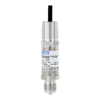
9WIKA operating instruction pressure transmitter, model A-10
EN
11218720.15 07/2018 EN/DE/FR/ES
5. Commissioning, operation
5. Commissioning, operation
5.1 Mounting the instrument
Only use the pressure transmitter if it is in perfect condition with respect to safety.
Prior to commissioning, the pressure transmitter must be subjected to a visual inspection.
■
Leaking uid is indicative of damage.
Requirements for mounting point
The mounting point must meet the following conditions:
■
Sealing faces are clean and undamaged.
■
Sucient space for a safe electrical installation.
■
For information on tapped holes and welding sockets, see Technical information IN 00.14 at www.wika.com.
■
Permissible ambient and medium temperatures remain within the performance limits. Consider possible restrictions
on the ambient temperature range caused by mating connector used.
→ For performance limits see chapter 9 “Specications”
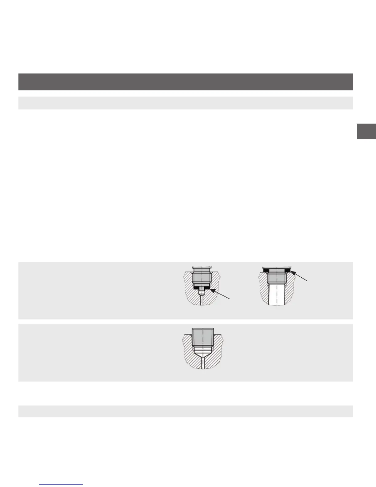
Sealing variants
Parallel threads
Seal the sealing face with flat gasket, lens-type
sealing ring or WIKA profile sealing.
per EN 837
per DIN 3852-E
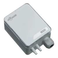
Tapered threads
Wrap threads with sealing material (e.g. PTFE
tape).
NPT, R and PT