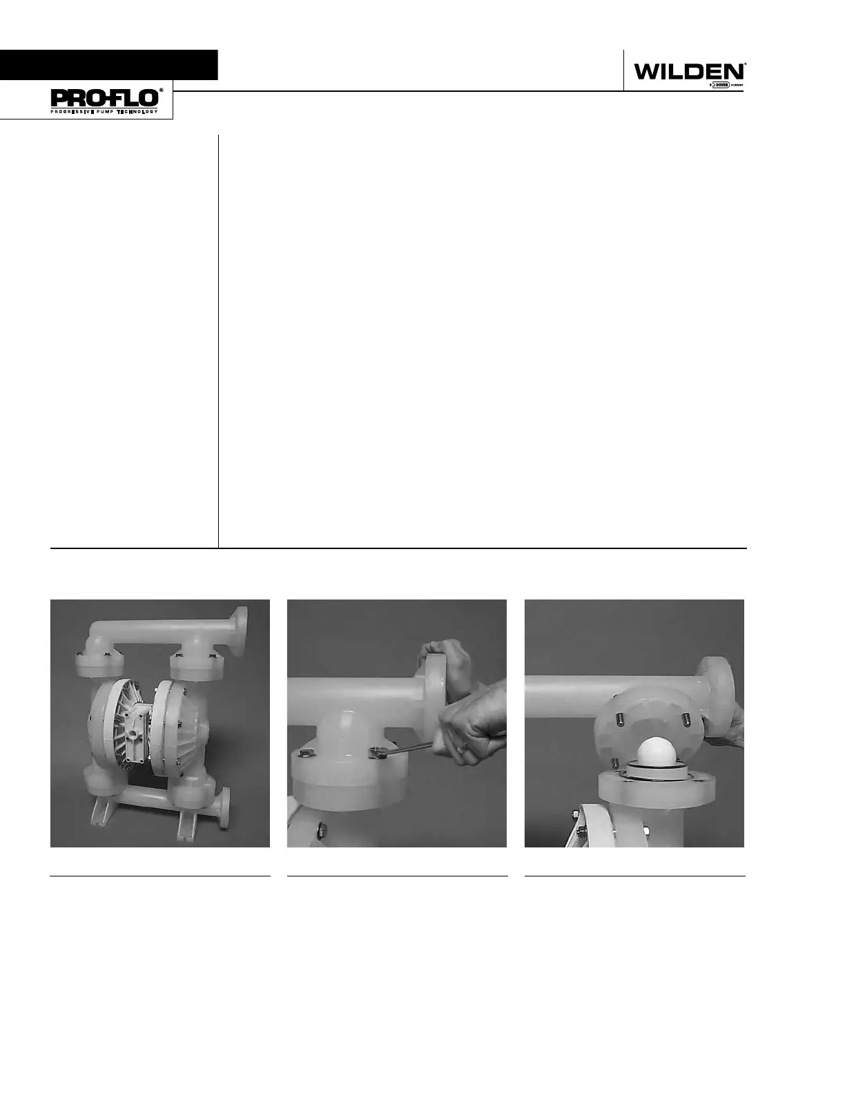
Step 1
Please note alignment marks on
liquid chambers. Use to properly
align center section with liquid
chamber.
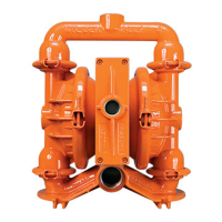
Step 2
Using a 3/4" wrench, loosen the
discharge manifold from the liquid
chambers.
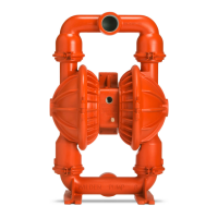
Step 3
Remove the discharge manifold to
expose the valve balls, valve seats
and valve seat o-rings.
Section 7
PUMP DISASSEMBLY
Tools Required:
• 3/4" Wrench
• Adjustable Wrench
• Vise equipped w/soft jaws
(such as plywood, plastic
or other suitable material)
CAUTION: Before any maintenance or repair is attempted, the compressed air line
to the pump should be disconnected and all air pressure allowed to bleed from the
pump. Disconnect all intake, discharge, and air lines. Drain the pump by turning it
upside down and allowing any fl uid to fl ow into a suitable container. Be aware of
any hazardous effects of contact with your process fl uid.
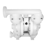
NOTE: The model photographed for these instructions incorporates PTFE diaphragms,
balls, and seats. Models with rubber diaphragms, balls and seats are the same except
where noted.
WILDEN PUMP & ENGINEERING, LLC 26 WIL-11250-E-03