11
Part Number 550-142-785/0812
GWI
Series 2 Gas-Fired Water Boilers – Boiler Manual
Direct exhaust venting continued
1. Donotmixtypesormanufacturersofventmaterials.
Useonlytheventstarterofthesamemanufacturer
astheventcomponents.Donotmixcomponents
fromdifferentsystems.Theventsystemcouldfail,
causing flue gas spillage, resulting in severe per-
sonal injury or death.
2. Clean all joints beforesealing.Seevent manufacturer’sin-
structionsforcleaningandsealingjoints.Usetheirspecied
sealant. Do not use screws.
3. Install ventpipewithseamsontop ofventhorizontalruns.
Followrequirementsonpage 10forventterminationlocation.
4. Maintainminimum2”clearancefromcombustiblematerials
to vent pipe.
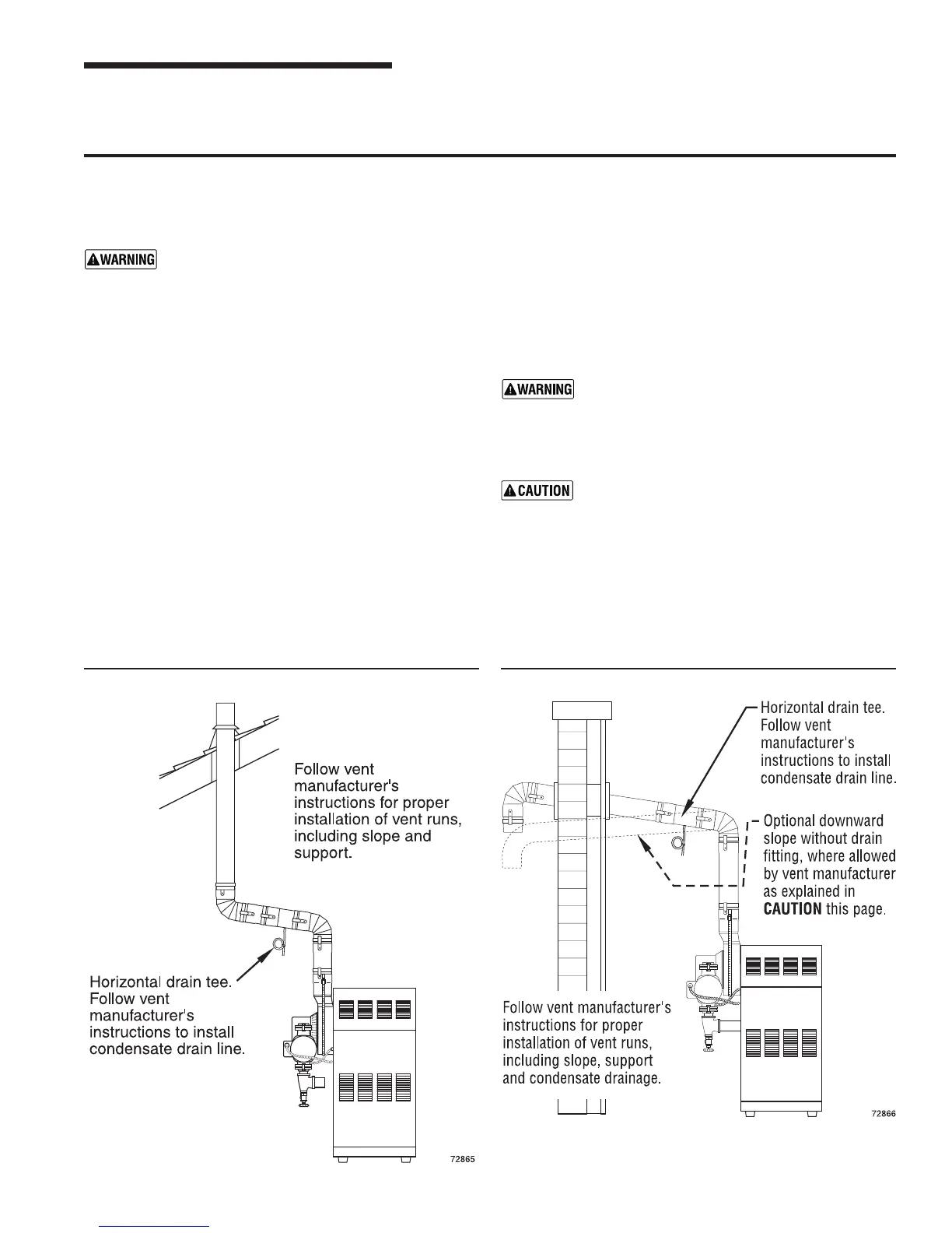
5. Vertical venting — See Figure 6.Followventmanufacturer’s
instructionsforventingthroughroof.
• Vent pipe must extend through roof ashing, jacket or
thimble.
• Vent may pass through oor, inside wall or concealed
space when installed according to vent manufacturer’s
instructions.
Sidewall venting — See Figures 7 and 8. Vent must terminate
atleastone footaboveanticipatedsnowline.Vent mustbe
terminated only with:
• Elbowwithintegralscreen.
• Elbowandterminationcouplingwithscreen(notavailable
forStaR-34).
6. Donotsealventpipe(slipconnectorforSaf-TVent)toinside
or outside plate.
7. Ifpassingthroughnoncombustiblewall,provideholediam-
eterlargeenoughtoinserttheventpipe(slipconnectorfor
Saf-TVent).
8. Installhorizontaldrainteeascloseaspossibletoboiler,in
first horizontal run. See Figure 7.
9. Do not exceed the maximum vent system length givenin
Table 4, page 9.
Condensatedrainline—useonlysiliconetubing
ratedforatleast400°Ffortherst18”ofconden-
sate drain line, then other non-metallic tubing may
beused.Usinganyothermaterialcouldcauseue
gasleakage,potentiallyresultinginseverepersonal
injury, death or substantial property damage.
On some installations, the condensate drain fitting
may be omitted, provided:
• Ventmanufacturershowsthisoptionintheirinstruc-
tions.
• Ventisslopedtowardterminationasshownindotted
lines in Figure 7.
• Theventisinstalledperboilermanufacturer’sand
ventmanufacturer’sinstructions.
Condensatedrippagefromsuchventsmayaccumulateonthe
groundbelow.Considertrafcintheareatoavoidhazarddueto
ice accumulation.
Installing direct exhaust vent and termination
3 Vent installation continued
Figure 6 Vertical direct exhaust installation Figure 7 Direct exhaust through side wall