13
Part Number 550-142-785/0812
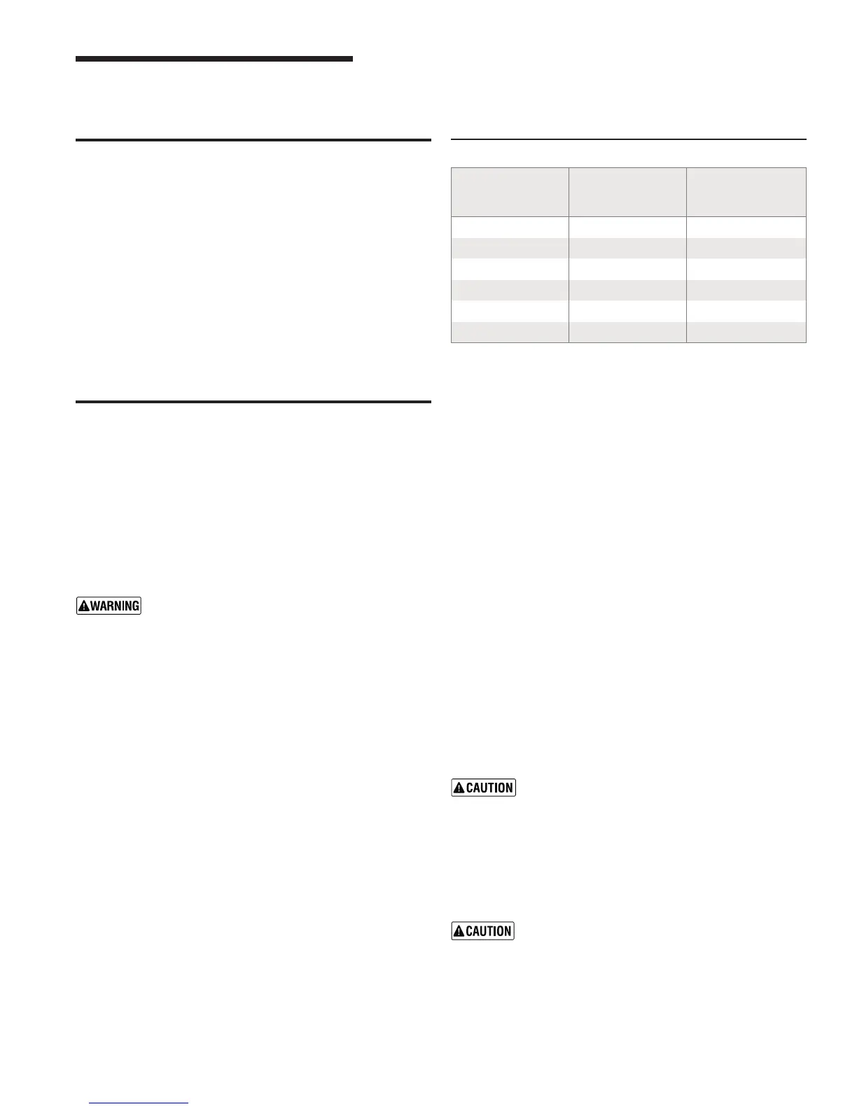
Table 6 Water pipe size (based on 20 °F rise)
General
Boiler
model
number
To
system
From
system
GWI-047
¾” ¾”
GWI-063
1” 1”
GWI-095
1” 1”
GWI-127
1” 1”
GWI-158
1 ¼” 1 ¼”
GWI-190
1 ¼” 1 ¼”
GWI
Series 2 Gas-Fired Water Boilers – Boiler Manual
IfinstallationistocomplywithASMEorCanadianrequirements,
anadditionalhightemperaturelimitisneeded.Installcontrolin
supply piping between boiler and isolation valve. Set second
controltominimum20°Fabovesetpointofrstcontrol.Maximum
allowablesetpointis240°F.Seepage 24 and 25forwiring.
Alowwatercutoffdeviceisrequiredwhenboilerisinstalledabove
radiation level or by certain state or local codes or insurance
companies.Uselowwatercutoffdesignedforwaterinstallations.
Electrodeprobe-typeisrecommended.Purchaseandinstall in
tee in supply piping above boiler.
Usebackowcheckvalveincoldwatersupplyifrequiredby
local codes.
See Figure 9(diaphragm-typeorbladder-typeexpansiontank)
orFigure10(closed-typeexpansiontank)onpage 14, and Table
6, fornear-boiler and single-zone systems designed for return
wateratleast130°F.
See page 13formultiple-zonepiping.
See page 14forboilersusedwithrefrigerationsystems.
Near-boiler piping
Relief valve
Installreliefvalveverticallyin¾”tappingonsideofboiler.See
thetagattachedtothereliefvalveformanufacturer’sinstructions.
To avoid water damage or scalding due to valve
operation, discharge line must be connected to re-
liefvalveoutletandruntoasafeplaceofdisposal.
Terminate the discharge line to eliminate possibility
ofsevereburnsshouldthevalvedischarge.
• Dischargelinemustbeasshortaspossibleandbe
the same size as the valve discharge connection
throughout its entire length.
• Dischargelinemustpitchdownwardfromthevalve
and terminate at least 6” above the floor drain where
any discharge will be clearly visible.
• Thedischargelineshallterminateplain,notthread-
ed,withamaterialserviceablefortemperaturesof
375°Forgreater.
• Donotpipethedischargetoanyplacewherefreez-
ing could occur.
• Noshutoffvalveshallbeinstalledbetweentherelief
valve and boiler, or in the discharge line. Do not plug
or place any obstruction in the discharge line.
• Failuretocomplywiththeaboveguidelinescould
resultinfailureofthereliefvalvetooperate,result-
inginpossibilityofseverepersonalinjury,deathor
substantial property damage.
• Testtheoperationofthevalveafterllingandpres-
surizingsystembyliftingthelever.Makesurethe
valvedischargesfreely.Ifthevalvefailstooperate
correctly,replaceitwithanewreliefvalve.
Circulator
The circulator is shipped loose (wiring pre-attached to boiler)
to allow you to locate it either in the return or supply piping, as
desired. See page 14foratypicalinstallation.Pipetheexpansion
tanktothesuctionsideofthecirculatorwheneverpossible.Install
anairseparatorinthesupplypiping.Connecttheexpansiontank
totheairseparatoronlyiftheseparatorisonthesuctionsideof
thecirculator.Alwaysinstallthesystemllconnectionatthesame
pointastheexpansiontankconnectiontothesystem.Figures 4
and 5 show typical near-boiler piping connections.
Expansion tank
Diaphragm- or bladder-type expansion tank — Figure 9,
page 14
1. Ensure expansion tank size will handle boiler and system
watervolumeandtemperature.Tankmustbelocatedinboiler
returnpipingasclosetoboileraspossible,beforeinletside
ofcirculator.Seetankmanufacturer’sinstructionsfordetails.
2. Installanautomaticairventasshown.
Closed-type expansion tank — Figure 10, page 14
1. Ensureexpansiontanksizewillhandleboilerandsystemwater
volumeandtemperature.Seetankmanufacturer’sinstructions
fordetails.
2. Connecttankto½”NPTtappinglocatedbehindsupplyoutlet,
using ½” NPT piping. Pitch any horizontal piping up towards
tank1inchper5feetofpiping.
Undersizedexpansion tanks cause system water
tobelostfromreliefvalveandmakeupwatertobe
addedthroughllvalve.Eventualsectionfailurecan
result.
Water piping — multiple zone systems
Installsystempipingusingeithercirculatorzoningorzonevalve
zoning.Installexpansiontankonsuctionsideofsystempump.
Alwaysconnectlllineonlyattheexpansion tank — neverat
another point in the system.
DO NOT connect directly from 3-wire zone
valves to the T-T terminals on the boiler
.
When using 3-wire zone valves, install an isolation
relay.Connectthezonevalveendswitchwiresto
theisolationrelaycoil.Connecttheisolationrelay
contact across the boiler T-T terminals. Failure to
comply can result in damage to boiler components
or cause unreliable operation, resulting in severe
property damage.
4 Install water piping4 Install water piping
 Loading...