20
Part Number 550-142-785/0812
GWI
Series 2 Gas-Fired Water Boilers – Boiler Manual
❏ Boilerandheatdistributionunitslledwithwater?
❏ Automaticairvent,ifused,openonefullturn?
❏ Airpurgedfromsystem?
❏ Airpurgedfromgaspiping?Pipingcheckedforleaks?
❏ Correctly-sized manifold orices installed? See Table 3,
page 6tochecksizeandfueltype.
Correctly sized manifold orices must be used.
Failure to do so will cause severe personal injury,
death or substantial property damage.
❏ Followed“Operatinginstructions”onboilerorinmanual,page
26forproperstart-up?
❏ Properburnerameobserved?See“Verifyoperation”,manual
Section 7.
❏ Test temperature limit — While burners are operating, turn
BoilerTempadjustmentknobcounterclockwiseuntildisplay
reading is below actual boiler water temperature. Burners
should go off while circulator continues to operate.Turn
BoilerTempadjustmentknobclockwiseuntildisplayread-
ingisaboveboilerwatertemperatureandignitionsequence
should resume.
❏ Test additional eld-installed controls—Ifboiler has a low
water cutoff, additional high limit or other controls, test for
operation as outlined by manufacturer. Burners should be
operatingandshouldgooffwhencontrolsaretested.When
controls are restored, burners should reignite.
❏ Testignitionsystemsafetydevice:
a. Connectmanometertooutletsideofgasvalve.Startboiler,
allowingfornormalstart-upcycletooccurandmainburn-
erstoignite.Withmainburnerson,manuallyshutoffgas
supplyatmanualmainshutoffgasvalve.Burnersshould
gooff.Openmanualmainshutoffgasvalve.Manometer
should confirm there is no gas flow. Pilot will relight, flame
sensing element will sense pilot flame and main burners
reignite.
❏ Setlimitcontrol(s)tosystemtemperaturerequirements.Adjust
balancing valves and controls to provide design temperature
to system.
❏
SetEconomymode,fullyclockwise.
❏ For multiple zones, adjust flow so it is about the same in each zone.
❏ Verifythermostatheatanticipator(ifavailable)setproperly?
See wiring diagram label on boiler or in manual, page 24 and
25.
❏ Cycleboilerwiththermostat—Raisetohighestsettingand
verify boiler goes through normal start-up cycle. Lower to
lowestsettingandverifyboilergoesoff.
❏
CycleDHWAquastatifused.
❏ Measurenaturalgasinput:
a. Operate boiler 10 minutes.
b. Turnoffotherappliances.
c. Atnaturalgasmeter,measuretime(inseconds)required
touseonecubicfootofgas.
d. Calculategasinput:
number of seconds from step c
= Btuh
e. Btuhcalculatedshouldapproximateinputratingonboiler
8 Checkout procedure
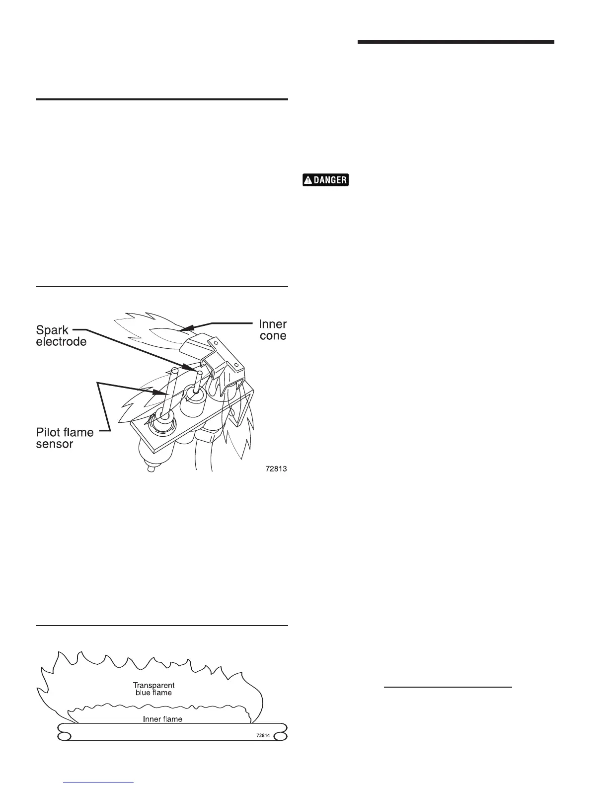
Check burner flame — Pilot burner
Proper pilot flame (see Figure 16):
1. Blue flame.
2. Innerconeengulngpilotamesensor.
3. Pilot flame sensor glowing cherry red.
Improper pilot flame:
1. Overred — Large ame lifting or blowingpast pilot ame
sensor.
2. Underred—Smallame.Innerconenotengulngpilotame
sensor.
3. Lackofprimaryair—Yellowametip.
Figure 17 Typical main burner ame
Verify operation
Figure 16 Typical pilot burner ame
4. Incorrectlyheatedpilotamesensor.
Check burner flames — Main burner
Proper main burner flame (see Figure 17):
1. Yellow-orangestreaksmayappear(causedbydust).
Improper main burner flame:
1. Overred—Largeames.
2. Underred—Smallames.
3. Lackofprimaryair—Yellowtippingonames(sootingwill
occur).
7 Start-up continued