31
Part Number 550-142-785/0812
GWI
Series 2 Gas-Fired Water Boilers – Boiler Manual
12 Troubleshooting
Labelallwirespriortodisconnectionwhenservic-
ing controls. Wiring errors can cause improper and
dangerous operation.
Neverjumper(bypass)rolloutthermalfuseelement
oranyotherdeviceexceptformomentarytestingas
outlinedin“Troubleshooting”charts,pages 34 - 40.
Severe personal injury, death or substantial property
damage can result.
Burner access panel must be in position during
boiler operation to prevent momentary flame rollout
onignitionofmainame.Severepersonalinjuryor
substantial property damage will result.
Before troubleshooting:
1. Havethefollowingitems:
a. Voltmeterthatcancheck120VACand24VAC.
b. Microammeterwithaminimumscalerangeof0-25.
c. Continuitychecker.
d. U-tubemanometer
e. Inclinedmanometerwith0–2”w.c.range.
2. Checkfor120VAC(minimum102VACtomaximum132VAC)
to boiler.
3. Makesurethermostatiscallingforheatandcontacts(includ-
ingappropriatezonecontrols)areclosed.Checkfor24VAC
between thermostat wire nuts and ground.
Check the following:
1. Wire connectors to control module are securely plugged in at
module and originating control.
2. Gaspressures(connectU-tubemanometeratgasvalvetap-
pings):
a. Withboileroff—13”w.c.maximumnaturalorpropane
gaspressureupstreamofgasvalve.
b. With boiler on:
• 5”w.c.minimumnaturalgaspressureor11”w.c.propane
gaspressureupstreamofgasvalve.
• 3.5”w.c.minimumnaturalgaspressureor10”w.c.propane
gaspressuredownstreamtappingongasvalve—Can
be adjusted by regulator on gas valve.
How to check pressure switch setting (if specified
in Troubleshooting charts
)
Make sure boiler water temperature is 100 °F or
coolerbeforestartingproceduretoobtainappropri-
ate readings.
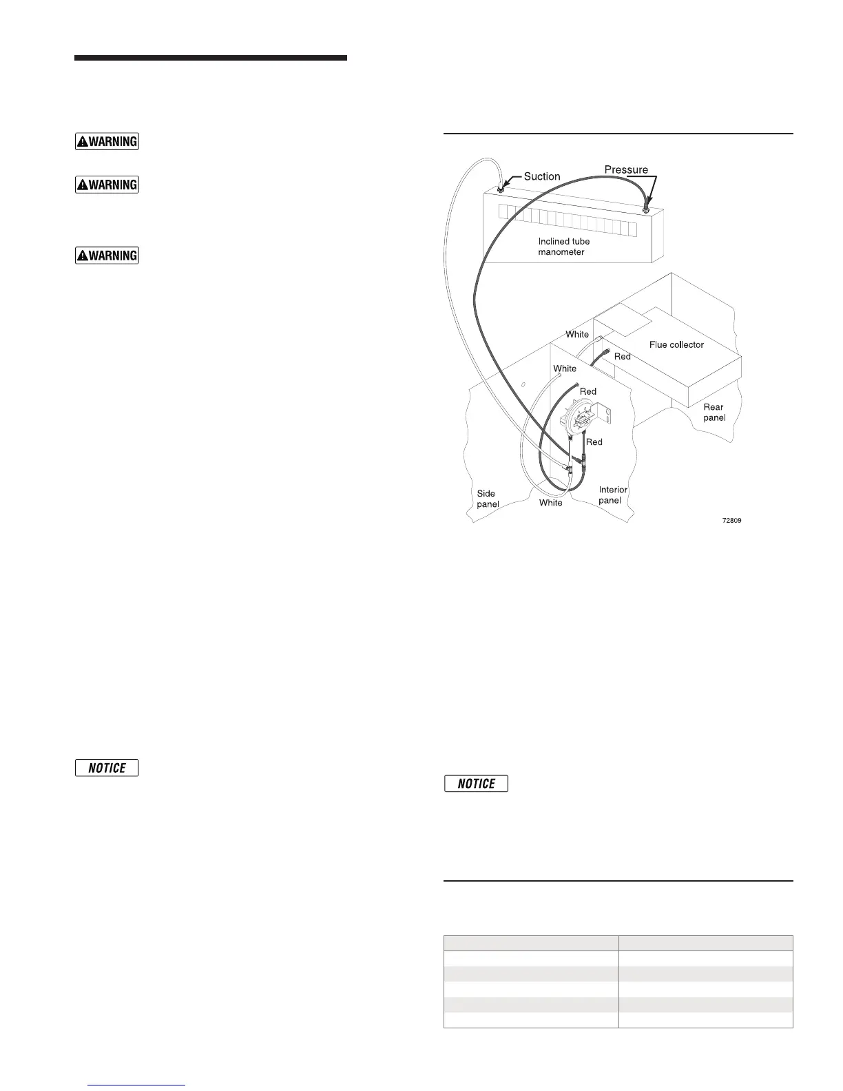
1. See Figure 21 and Table 9.
2. Removeboth air pressure switchhoses from air pressure
switch.
3. Install tees and tubing as shown in Figure 21 to inclined
manometer.
4. Turnoffgasvalveandsetthermostattocallforheat.Inducer
will run but burners will not ignite.
5. Checkfor24VACbetweenbothairpressureswitchterminals.
6. Ifmanometerreadingisabovethesetpointoftheswitch(see
Table 9),butthereisnot24VACbetweenairpressureswitch
terminals“C”and“NO”—replaceairpressureswitch.
Troubleshooting air pressure reading
1. Ifmanometerreadingislowerthanthesetpointoftheswitch
(seeTable 9)—checkforpossiblecauses:
• blockageinhoses
• obstructionininducerhousingoutlet
• looseinducerwheelonmotorshaft
• inducermotornotinproperrpm
• inducerbackplatenotsealedproperly
• blockageinblockassembly
• blockageinuepipeortermination
• incorrectpressureswitch
Return to normal operation
When pressure reading is correct and air pressure switch is
operating properly — remove tees and reinstall hoses to air
pressure switch.
The boiler will not operate correctly unless pressure
switch hoses are correctly located. The red hose
connectsfromtherightside(negative)hosebarb
totheuecollector.Thewhitehoseconnectsfrom
theleftside(positive)hosebarboftheswitchtothe
connectorbox(betweenuecollectorandinducer)
as shown in Figure 21.
Table 9 Pressure switch setpoint (for elevations
above 2,000 ft, contact your local supplier for
details.)
Boiler model number Inches W.C.
GWI-047 and GWI-063
1.19
GWI-095
1.08
GWI-127
0.86
GWI-158
0.61
GWI-190
0.76
Figure 21 Checking pressure switch