17
Part Number 550-142-785/0812
GWI
Series 2 Gas-Fired Water Boilers – Boiler Manual
Foryoursafety,turnoffelectricalpowersupplyat
serviceentrancepanelbeforemakinganyelectrical
connectionstoavoidpossibleelectricshockhazard.
Failure to do so can cause severe personal injury
or death.
WiringmustbeN.E.C.Class1.
If rollout thermal fuse element wire as supplied
withboilermustbereplaced,type200°Cwireor
equivalentmustbeused.Ifotheroriginalwiringas
supplied with boiler must be replaced, use only type
105°Cwireorequivalent.
Boilermustbeelectricallygroundedasrequiredby
NationalElectricalCodeANSI/NFPA70-latestedition.
Electrical installation must comply with:
1. NationalElectricalCodeandanyothernational,state,provin-
cial or local codes or regulations.
2. InCanada,CSAC22.1CanadianElectricalCodePart1,and
any local codes.
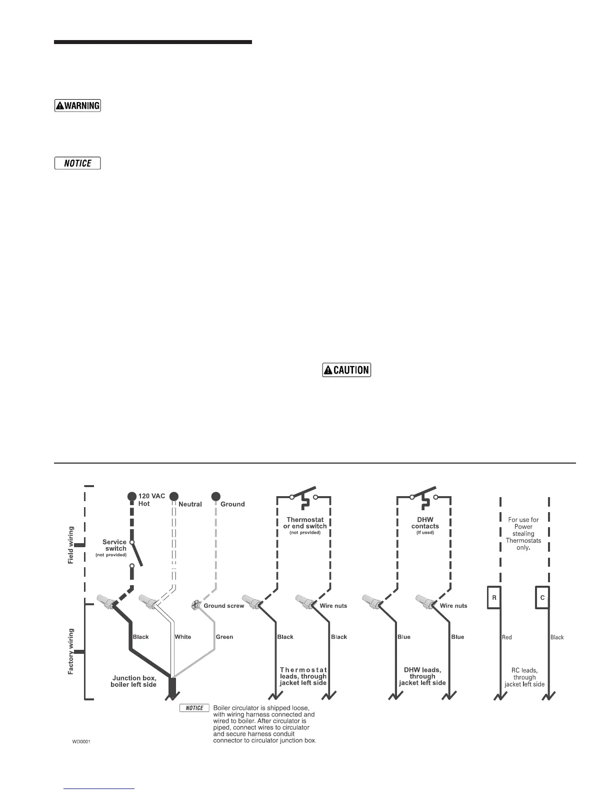
Wiring connections
Boiler is shipped with controls completely wired. See wiring dia-
gram on page 24 and 25fordetails.Circulatorisshippedloose,
butwiringharnessispre-attachedtotheboiler.Connectwiresin
circulatorjunctionbox.
Thermostat
1. Connectthermostatasshownonwiringdiagramonboiler.
2. Installoninsidewallawayfrominuencesofdrafts,hotorcold
waterpipes,lightingxtures,television,sunraysorreplaces.
3. If thermostat has a heat anticipator,set heat anticipatorin
thermostattomatchpowerrequirementsofequipmentcon-
nectedtoit.Ifconnecteddirectlytoboiler,seeWiringdiagrams,
6 Field wiring
page 24 and 25,foranticipatorsetting.Forotherdevices,see
manufacturer’sspecications.Wiringdiagramonboilergives
settingforcontrolmoduleandgasvalve.Alsoseeinstructions
with thermostat.
DHW (if used)
ConnectDHWaquastatasshowninwiringbelow.Economy
functionisn’tutilizedwithDHWinput.
R & C Connections (if used)
24Vacleadsshouldbeusedforpowerstealingthermostatsonly!
Junction box (furnished)
1. Connect120VACpowerwiring(Figure 15).
2. Fuseddisconnectorserviceswitch(15amp.recommended)
maybemountedonthisbox.Forthoseinstallationswithlocal
codeswhichprohibitinstallationoffuseddisconnectorservice
switchonboiler,installa2x4coverplateontheboilerjunction
boxandmounttheserviceswitchremotelyasrequiredbythe
code.
Wiring multiple zones
Seezonevalvemanufacturer’sliteratureforwiringandapplication.
Aseparatetransformerisrequiredtopowerzonevalves.Zoning
withcirculatorsrequiresarelayforeachcirculator.
DO NOT connect directly from 3-wire zone
valves to the T-T terminals on the boiler
.
When using 3-wire zone valves, install an isolation
relay.Connectthezonevalveendswitchwiresto
theisolationrelaycoil.Connecttheisolationrelay
contact across the boiler T-T terminals. Failure to
comply can result in damage to boiler components
or cause unreliable operation, resulting in severe
property damage.
Figure 15 Field wiring connections — service switch, DHW (if used) and thermostat (or end switch) provided by installer