32
Part Number 550-142-785/0812
GWI
Series 2 Gas-Fired Water Boilers – Boiler Manual
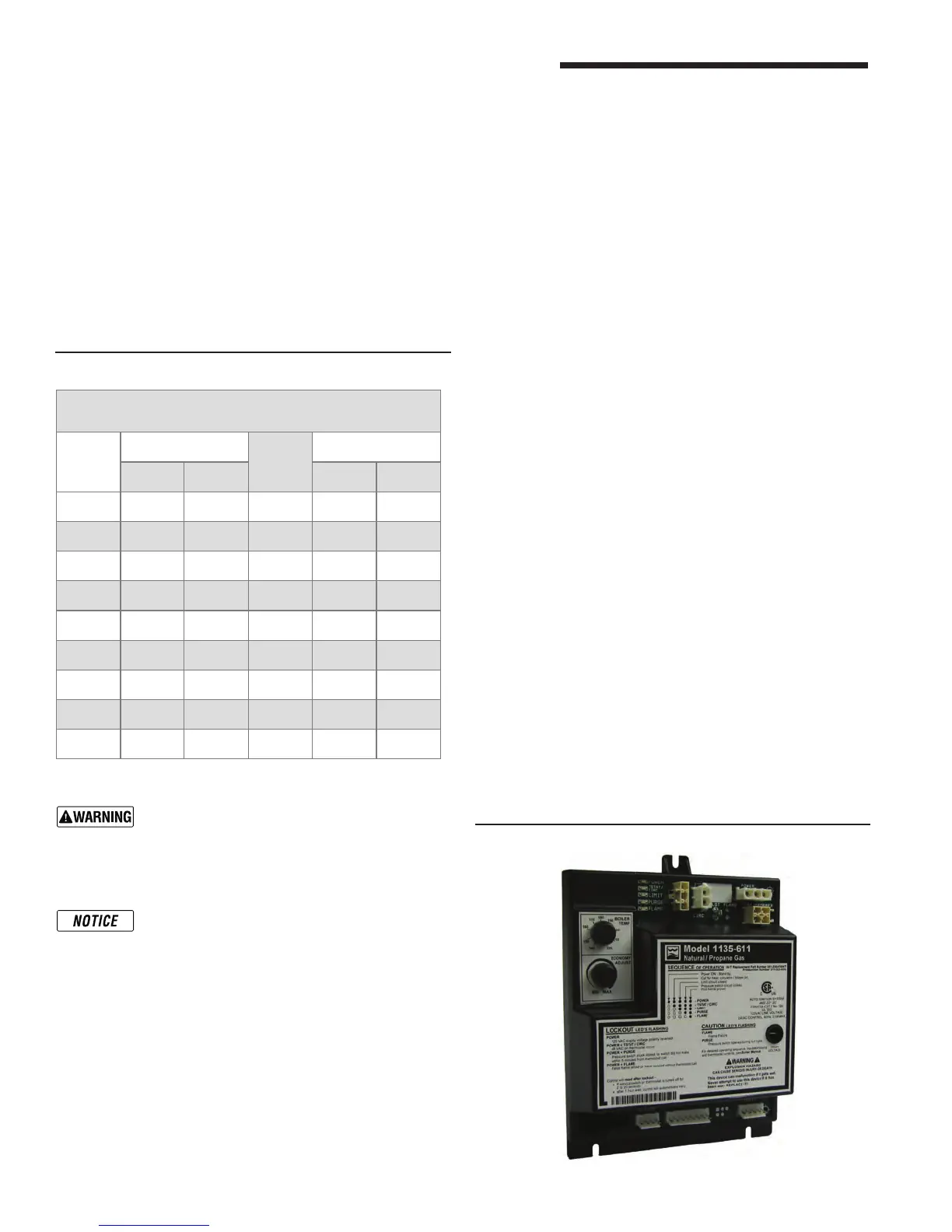
Control module
Solder or water splatter between plugs and circuit
board can cause improper operation of control
module. Place a shield over the boiler internal con-
trols and components during installation. Failure to
comply could result in severe personal injury, death
or substantial property damage.
Make sure ground wiring is installed per wiring
diagram. Good grounding is extremely important
forproperoperation.
Control indicator lights —
LOCKOUT modes
See Charts 1 through 7 in this section for detailed trouble-
shooting procedures.
Control indicator lights —
HARD LOCKOUT Summary (Flashing LED’s)
MAY remove 120VAC power for more than 2 seconds to clear
lockout OR ignition control will automatically restart sequence
of operation after 1 hour waiting period after fault condition is
cleared.
12 Troubleshooting – components (continued)
INDICATOR LIGHT CONDITION
POWER
Flashes once per second 120 VAC connection to
boiler reversed.
Flash code 2* Internal fault, icroprocessor
or memory.
Flash code 3* Unused.
Flash code 4* Unused.
Flash code 5* Internal fault, water
thermistors disagree.
Flash code 6* Internal fault, gas valve
circuit.
* Flash code pattern: POWER LED ashes 2, 3, etc. times
rapidly followed by 2 seconds off, then repeats.
SOFT LOCKOUT Summary (Flashing LED’s)
MAY remove 120VAC power for more than 2 seconds, cycle
thermostat for between 2 and 20 seconds, OR ignition control
will automatically restart sequence of operation after 1 hour
waiting period.
INDICATOR LIGHT CONDITION
POWER + TSTAT/CIRC High voltage detected on TSTAT circuit.
POWER + PURGE Pressure Switch stuck open or closed.
POWER + FLAME Flame sensed without call for heat or out
of sequence during ignition trial.
CAUTION Summary (Flashing LED’s)
INDICATOR LIGHT CONDITION
PURGE Pressure switch opened after it had been
proven closed.
LIMIT Fault detected in temperature sensing
hardware.
FLAME Flame loss or ame not sensed during
trial for ignition.
Troubleshooting the control module
See Figure 23, page 33, for location of harness plug receptacles
and plugs on the control module.
Sensor resistance values
Temp
(°F)
Sensor ohms
Temp
(°F)
Sensor ohms
Min Max Min Max
32 34265 37871 120 4517 4992
40 27834 30764 130 3698 4088
50 21630 23907 140 3043 3364
60 16944 18727 150 2517 2782
70 13372 14780 160 2091 2311
80 10629 11747 170 1744 1928
90 8504 9399 180 1461 1615
100 6847 7568 190 1229 1359
110 5545 6129 200 1038 1147
Temperature sensor
1. The boiler temperature sensor is a resistance-type device.
2. The Chartbelowshowsthecorrectvalueforthesensorat
various temperatures.
3. Usetheresistancevaluesat32°F,60°F,70°Fand212°Fto
measurethesensorresistanceatknowntemperatures(ice
point,roomtemperatureandsealevelboilingpoint).Forice
point and boiling point, insert the sensor in water at that tem-
perature.Useanohmmetertoreadresistancevaluebetween
thermister # and thermistor common. See Figure 30, page 50,
forsensorplugdetails.
Sensor resistance values
Figure 22 Control module