9
Part Number 550-142-785/0812
Table 4 Maximum vent length
Max.vent length
(feet)
Total number of 90° elbows
(Notes 1 & 2)
1 2 3 4 5 6
GWI-047 to GWI-158
55 48 41 34 27 20
GWI-190
35 28 21 14 7 --
Notes:
1. Do not include termination fitting when counting total number of elbows.
2. One (1) 90° elbow is equivalent to two (2) 45° elbows.
GWI
Series 2 Gas-Fired Water Boilers – Boiler Manual
Direct exhaust venting
Obtain vent system components
1. ThefollowingspecialgasventsystemscomplywithUL-1738
andULC-S636standardsandarecertiedbyCSAastheonly
systemssuitableforusewithGWIboilers(all3”diameter):
• Heat-Fab,Inc.Saf-TVent
®
• Flex-LInternational,Inc.StaR-34
• Z-Flex
®
,Inc.Z-VentII
• ProTechSystemsFasNSeal™
Useonlytheventstarterofthesamemanufacturer
astheventcomponents.Donotmixcomponents
fromdifferentsystems.Theventsystemcouldfail,
causing flue gas spillage, resulting in severe per-
sonal injury or death.
2. Selectverticalorsidewallventingdependingonjobrequire-
ments.
3. RefertoTable4formaximumventrunlengthsandnumberof
elbows.DonotexceeddatainTable 4.
4. SelectventcomponentsfromseparateGWI Vent Component
Supplement.Allcomponents,includingtheventstarter,must
beofthesameventmanufacturer.Donotmixcomponents.
1. Select a vent pipe manufacturer from separate GWI Vent
Component Supplement and obtain all vent components
needed, based on boiler location and venting method.
2. Youmustusetheventstarter(seebelow)madebytheventpipe
manufacturer.SeeGWI Vent Component Supplementfor
partnumberofeachcomponent,listedbyventmanufacturer.
Useonlytheventstarterofthesamemanufacturer
astheventcomponents.Donotmixcomponents
fromdifferentsystems.Theventsystemcouldfail,
causing flue gas spillage, resulting in severe per-
sonal injury or death.
3. Follow all applicable national, state, local or provincial codes
whenventingtheGWIboiler.
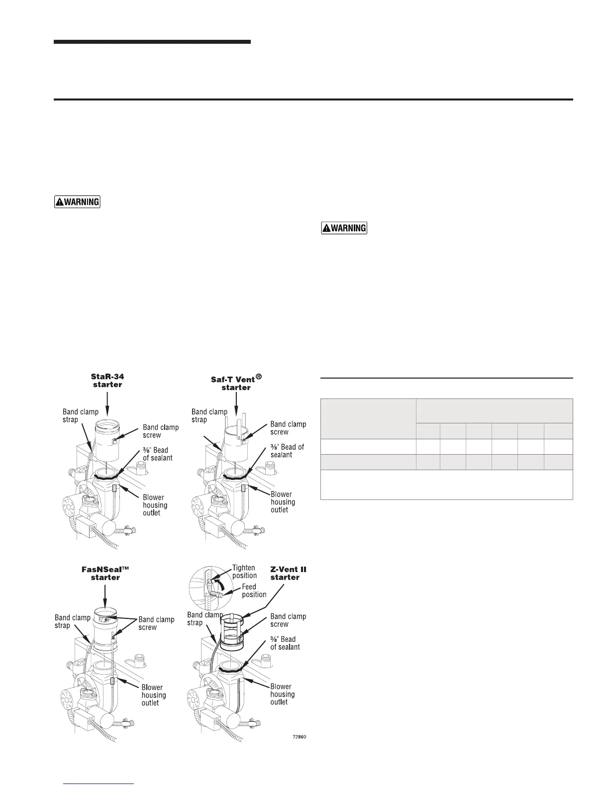
4. Connectventstartertoblowerhousingoutletasshownbelow.
a. Donotmixcomponentsfromdifferentventmanufacturers.
b. Maintainminimum2”clearancefromcombustiblematerials
to vent pipe.
c. Seal with sealant specied byventpipe manufacturer,
using
3
/
8
”bead(notrequiredforFasNSeal™).
d. Tighten strap at band clamp screw until strap is snug
around blower housing.
3 Vent installation continued