Installation en
Installation and operating instructions Wilo-Control MS-L 21
L
1 2 3 4
PE
1~230 V
50/60 Hz
N
4
7
PE
ON DIP
1 2 3 4 5 6 7 8
8
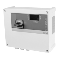
Fig.6: Mains connection 1~230V without
main switch
4 Terminal strip: Earth
7 Terminal strip: Mains connection
8 DIP switch1
NOTICE!Install two cable bridges on the mains terminal strip: Terminal 1/2 and ter-
minal 3/4.
ƒ Cable: 3-core
ƒ Terminals: 1 (L), 4 (N)
ƒ Connect the protective earth conductor (PE) to the terminal strip: earth (;).
ƒ DIP switch1, DIP8: OFF
Control MS-L...-O: Mains connection 3~400V, without main switch
L1
1 2 3 4
L2 L3
PE
3~400 V
50/60 Hz
N
7
4
PE
ON DIP
1 2 3 4 5 6 7 8
8
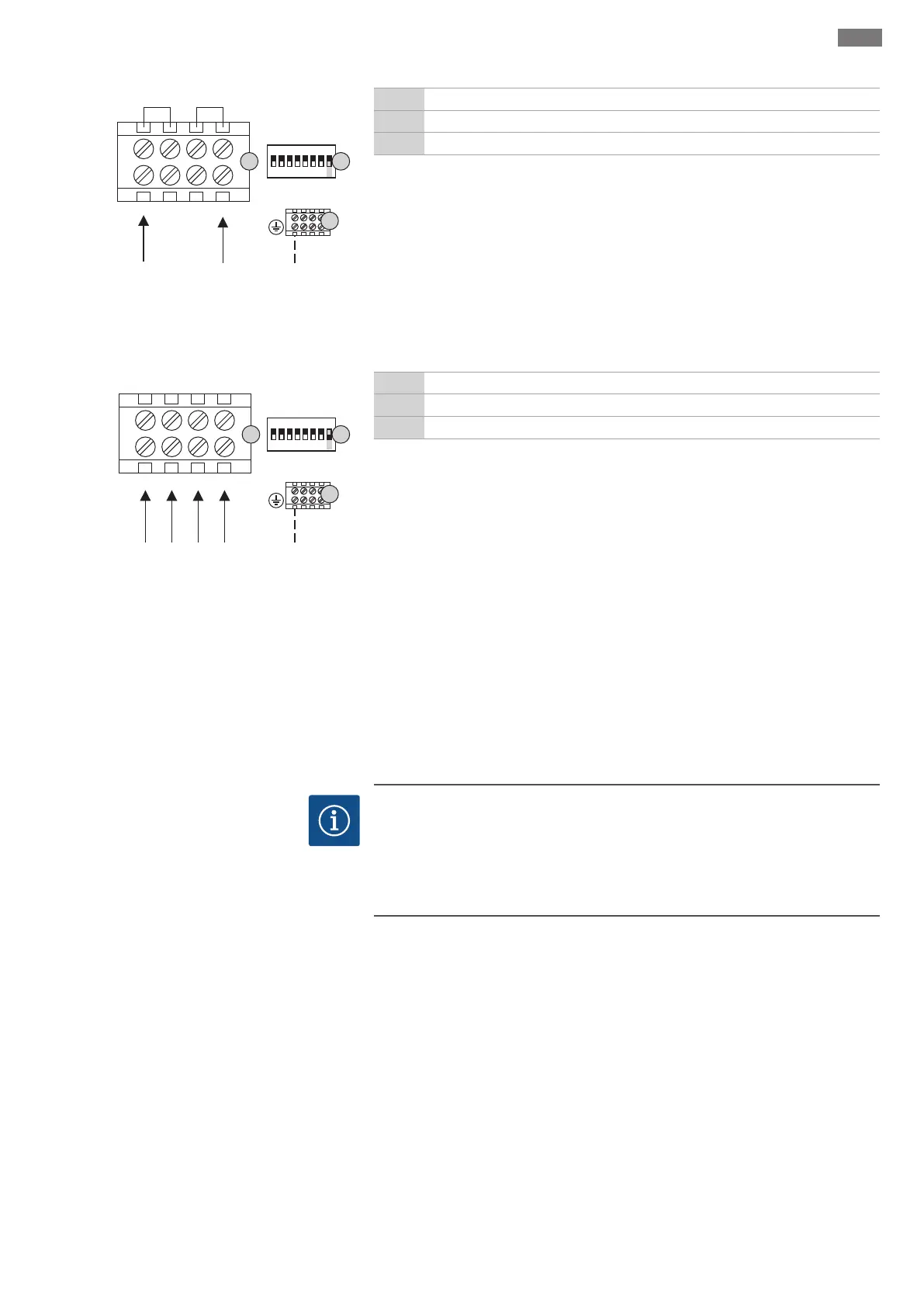
Fig.7: Mains connection 3~400V without
main switch
4 Terminal strip: Earth
7 Terminal strip: Mains connection
8 DIP switch1
NOTICE!Do not install any cable bridges on the mains terminal strip!
ƒ Cable: 5-core
ƒ Terminals: 1 (L1), 2 (L2), 3 (L3), 4 (N)
ƒ Connect the protective earth conductor (PE) to the terminal strip: earth (;).
ƒ DIP switch1, DIP8: ON
ƒ There must be a clockwise rotating field!
Control MS-L...-LS: with plug, for lifting units
Mains connection is established by inserting the plug into a socket:
ƒ 1~230V: Shock-proof socket or CEE32-socket
ƒ 3~400V: CEE16-socket
Install the socket in an overflow-proof manner in a radius of 1m from the switchgear.
6.5.4 Mains connection, pump
NOTICE
Rotating field, power supply and pump connection
The rotating field is routed from the mains connection directly to the pump connec-
tion. Check the required rotating field of the pumps to be connected (clockwise or
counter-clockwise)! Observe the installation and operating instructions of the
pumps.

 Loading...