en Installation
22 WILO SE 2020-05
M
3~
M
1~
T1
1 3 5 13 A1
2 4 6 14 A2
T2 T3
L1 L2 L3 NO
PE
2
4
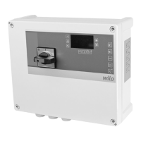
Fig.8: Pump connection
2 Motor contactor
4 Earth terminal
Insert the connection cables laid by the customer through the threaded cable glands
and secure. Connect the wires to the contactor as per the connection diagram:
Control MS-L.../MS-L...-O
ƒ Terminal assignment 1~230V
L = 4/T2, N = 6/T3, PE = earth terminal
ƒ Terminal assignment 3~400V
U = 2/T1, V = 4/T2, W = 6/T3, PE = earth terminal
bn = 2/T1, bk = 4/T2, gy = 6/T3, PE = earth terminal
Control MS-L...-LS
ƒ Terminal assignment 1~230V
L = 4/T2, N = 2/T1, PE = earth terminal
ƒ Terminal assignment 3~400V
U = 2/T1, V = 4/T2, W = 6/T3, PE = earth terminal
bn = 2/T1, bk = 4/T2, gy = 6/T3, PE = earth terminal
6.5.5 Adjust motor current monitoring
The electronic motor current monitoring monitors the rated current of the connected
pump. Set rated current according to rating plate:
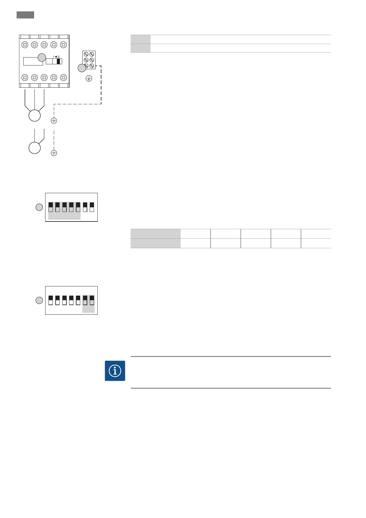
Fig.9: DIP switch1: Adjust motor current mon-
itoring
ƒ Set rated current via DIPs1-5 on DIP switch1.
ƒ Minimum rated current: 1.5A. All DIPs are in the “OFF” position.
ƒ The current value is increased by the value of the respective DIP by activating the in-
dividual DIPs (“ON” position).
ƒ Max. rated current: 12A.
DIP
1 2 3 4 5
Current value
0.5A 1.0A 2.0A 3.0A 4.0A
Example: required rated current 7.5A
1.5A + 2.0A (DIP3) + 4.0A (DIP5) = 7.5A
6.5.6 Switch on pumps (only Control
MS-L2...)
The connected pumps are switched on via DIPs6 and 7 on DIP switch2:
Fig.10: DIP switch2: Switch on pumps
ƒ The factory setting for both DIPs is “OFF”. Level control dependent activation of the
pumps is not possible.
ƒ Switch on pump 1: Set DIP6 to “ON”.
ƒ Switch on pump 2: Set DIP7 to “ON”.
6.5.7 Connection, thermal motor mon-
itoring
NOTICE
Do not apply external voltage!
An external voltage which is applied destroys the component.
 Loading...