Installation en
Installation and operating instructions Wilo-Control MS-L 23
GL
WSK
-P2
WSK
-P1
SL
10987654321
HW
HWGL
WSK
654321
3
3
Control MS-L1.../MS-L...-O
WSK
6521
3
Control MS-L1...-LS
Control MS-L2.../MS-L...-O
WSK
-P2
Sensor
+ ln
Sensor
+ ln
WSK
-P1
1094321
3
Control MS-L2...-LS
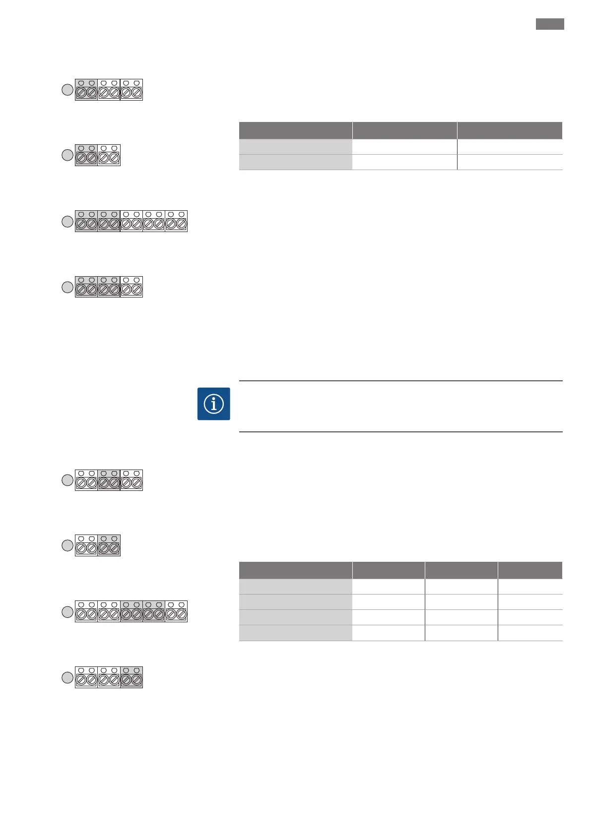
Fig.11: Terminal strip sensors: thermal motor
monitoring
Connect one thermal motor monitoring device with bimetallic strips per pump. Do not
connect a PTC sensor!
Insert the connection cables laid by the customer through the threaded cable glands
and secure. Connect the wires to the terminal strip according to the connection dia-
gram.
Switchgear Pump 1 Pump 2
Control MS-L1...
Terminal 1/2
Control MS-L2...
Terminal 1/2 Terminal 3/4
NOTICE!If a winding monitor is connected, remove the converter bridge installed at
the factory!
6.5.8 Connection of signal transmitter
for level control device
NOTICE
Do not apply external voltage!
An external voltage which is applied destroys the component.
GL
WSK
-P2
WSK
-P1
SL
10987654321
HW
HWGL
WSK
654321
3
3
Control MS-L1.../MS-L...-O
WSK
6521
3
Control MS-L1...-LS
Control MS-L2.../MS-L...-O
WSK
-P2
Sensor
+ ln
Sensor
+ ln
WSK
-P1
1094321
3
Control MS-L2...-LS
Fig.12: Terminal strip sensors: Level detection
connection
Control MS-L.../MS-L...-O
Connect float switch for the level detection. Level detection with a level sensor or elec-
trodes is not possible!
Control MS-L...-LS
A rod float sensor is used for the level detection. The sensor is installed in the lifting
unit at the factory. Level detection with float switches or electrodes is not possible!
Insert the connection cables laid by the customer through the threaded cable glands
and secure. Connect the wires to the terminal strip according to the connection dia-
gram.
Switchgear Base load (GL) Peak load (SL) Sensor
Control MS-L1.../MS-L1...-O
Terminal 3/4 − −
Control MS-L1...-LS
− − Terminal 5/6
Control MS-L2.../MS-L2...-O
Terminal 5/6 Terminal 7/8 −
Control MS-L2...-LS
− − Terminal 9/10
 Loading...