en
18 Installation and operating instructions • Wilo-Control SC2.0-Booster • Ed.01/2023-09
The motor protection is also active in manual mode and leads to deactivation of the corre-
sponding pump.
In the SCe version, the pump motors protect themselves by mechanisms integrated in the
frequency converters. The error messages from the frequency converters are handled in the
control device as described above.
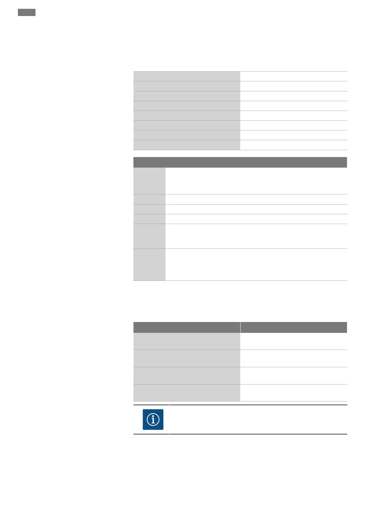
5.4 Technical data
Mains supply voltage 3~380/400V (L1, L2, L3, PE)
Frequency 50/60 Hz
Control voltage 24 VDC; 230 VAC
Max. current consumption See rating plate
Protection class IP54
Max. fuse protection on mains side See circuit diagram
Ambient temperature 0°C to +40 °C
Electrical safety Pollution degree 2
5.5 Type key
Example: SC-Booster 2x6.3A DOL FM
SC Version:
• SC = Control device for fixed-speed pumps
• SCe = Control device for electronically controlled variable-speed pumps
Booster Control for pressure-boosting systems
2x Max. number of pumps that can be connected
6.3A Max. rated current per pump in amperes
DOL
SD
Pump activation type:
- DOL = direct start (Direct online)
- SD = star-delta starting
FM
BM
WM
Installation type:
- FM = Control device is mounted on the base frame (frame mounted)
- BM = Floor model (base mounted)
- WM = Control device is mounted on a mounting bracket (wall mounted)
5.6 Scope of delivery
• Control device
• Circuit diagram
• Installation and operating instructions
• Factory test protocol
5.7 Accessories
Optional Description
Communication module "ModBus RTU" Bus communication module for "ModBus
RTU" networks
Communication module "BACnet MSTP" Bus communication module for "BACnet
MSTP" networks (RS485)
Communication module "BACnet IP" Bus communication module for "BACnet IP"
networks
WiloCare 2.0 Connection to internet-based remote
maintenance
NOTICE
Only one bus option can be active at any given time.
Other options on request
• Order accessories separately.