en
Installation and operating instructions • Wilo-Control SC2.0-Booster • Ed.01/2023-09 9
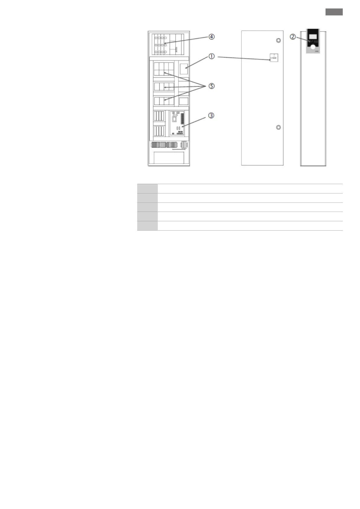
Fig.3: SC star-delta starting
1 Main switch
2 Human-Machine Interface (HMI)
3 Base board
4 Fuse protection of drives
5 Contactors/contactor combinations
The control device consists of the following main components:
• Main switch: Switches the control device on/off (item1)
• Human-machine interface (HMI): LCD display for viewing operating data (see menus),
LEDs for displaying the operating status (operation/fault), operating button for menu
selection and parameter input (item2)
• Base board: Printed circuit board with microcontroller (item3)
• Fuse protection of drives: Protection of the pump motors
In the DOL version: Motor protection switch
In the SCe version: Circuit breaker for the fuse for the pump mains supply cable (item4)
• Contactors/contactor combinations: Contactors for switching on the pumps. In SD (star-
delta starting) version control devices, including the thermal tripping devices for over-
current protection (default value: 0.58×IN) and the time relay for the star-delta
switchover (item5)
5.2 Functional principle
The Smart control system, controlled by a microcontroller, is used to control and regulate
pressure-boosting systems with up to 4 single pumps. The pressure of a system is meas-
ured with corresponding pressure transmitters and controlled in a load-sensitive way.
SCe
Each pump has an integrated frequency converter. In the constant pressure control mode
(p-c), only the base-load pump carries out the speed control. In the variable pressure (p-v)
control mode, all pumps are controlled and run at the same speed, except when a pump
starts or stops.
SC
All pumps are fixed speed pumps. The pressure control is a 2-point control. Non-controlled
peak-load pumps are switched on and off automatically depending on the load require-
ment.