English
Installation and operating instructions Wilo-CC-System 27
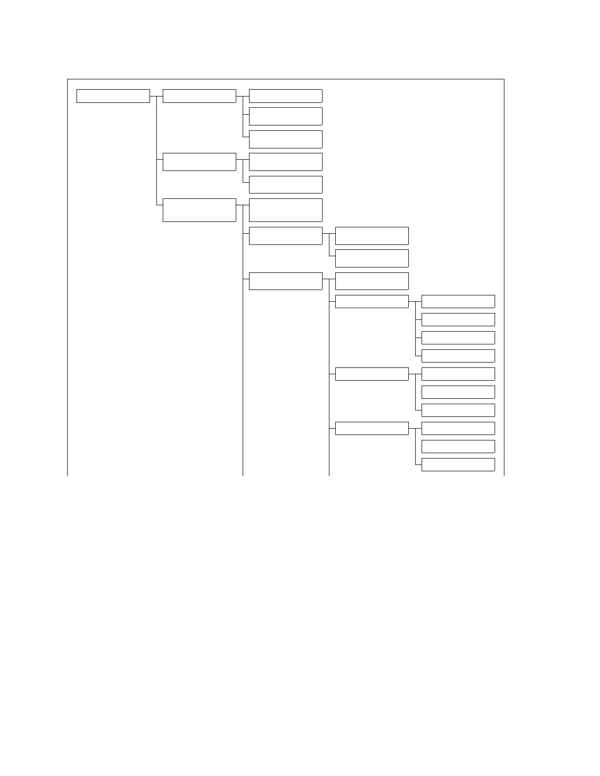
6.2.2 Menue structure
The system's menue is structured as follows:
A description of the menue functions is shown in
table 2.
Main menue 0
(Pump status, actual value
Pump 1...6 1
(Operation mode, -data, Info)
Operation mode Pump 1.1
(Manual, OFF, Automatic)
Operation data Pump 1.2
(Running hours day/overall, switch-
ing actions)
Info Pump 1.3
(Type, Output power P
2
, Nominal
current)
Diagram 2
(Actual value of controlled data, FC
frequency)
Trigger adjustments 2.1
(Time rate for data sampling dia-
gram in s)
Simulation 2.2
(Default values for commisioning/
tests)
Main menue 3
(Login/out, Fault messages, param-
eter settings, password administra-
tion, Site infos)
Login/Logout 3.1
Faulty messages 3.2
(recent messages, list, SMS adjust-
ments)
Fault message list 3.2.1
SMS adjustments 3.2.2
(4 pages: SMS messager, priorities,
station name, phone numbesn)
Parameter setup menues 3.3
(3 pages)
Operation mode of site 3.3.1
(Automatic with/without FC, drives
ON/OFF)
Operation parameter 3.3.2 1. Set value 3.3.2.1
2. Set value 3.3.2.2
Limit values 3.3.2.3
Sensor 3.3.2.4
Controller parameter 3.3.3 Base load pump 3.3.3.1
(2 pages: Input in ’bar’ or ’%’)
Peak load pump 3.3.3.2
(2 pages: Input in ’bar’ or ’%’)
PID-Regler 3.3.3.3
(Adjustment of kp, Ti, Td; Auto-PID)
Pump parameter 3.3.4 Number of pumps 3.3.4.1
(with/without reserve pump)
Pump change 3.3.4.2
(change mode, times)
Pump kick 3.3.4.3
(times, test)