en
16 WILO SE 2021-01
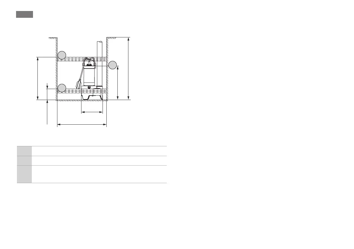
5.2.1 Stationary wet well installation
min. 450x450 mm
min. 18x18 "
min. 500 mm
min. 20 "
335 mm
13 "
216 mm
8,5 "
113 mm
5 "
416 mm
16 "
1
2
3
Fig.2: Installation dimensions and switching points
1 Switch-on level
2 Switch-off level
3
Minimum water level for continuous duty (S1). From
here only intermittent periodic duty (S3)
For stationary wet well installation, the pump is installed dir-
ectly onto the pressure pipe. Observe and adhere to the fol-
lowing points:
ƒ The connected pressure pipe must be self-supporting.
The pressure pipe must not be supported by the pump.
ƒ The pump may oscillate slightly during operation. These
oscillations must be dissipated via the pressure pipe.
ƒ Ensure that the connection to the pressure pipe is stress-
free– do not screw it in too tightly.
ƒ The pressure pipe must not be smaller than the pump’s
discharge connection.
ƒ Seal pipe connections with Teflon tape.
ƒ Install all specified valves in accordance with local require-
ments (gate valve, non-return valve).
ƒ Lay the pressure pipe frost-proof.
ƒ Avoid air intake! Air in the pump and in the pipe system
can lead to delivery problems. Air pockets must be re-
moved using the ventilation systems!
ƒ Install the pressure pipe as a “pipe loop” to avoid backflow
from the public sewer.
At its highest point, the bottom edge of the pipe loop
must be above the locally determined backflow level!
‡ Site is prepared.
‡ Pressure pipe properly installed.
1. Screw the discharge pipe fully into the pump’s discharge
connection.
2. Position the pump at the installation site.
CAUTION!Use a hard surface or underlay at the in-
stallation site to prevent sinking on soft substrate.
 Loading...