A l e x i A O w n e r ’ s M A n u A l
34
Wilson Audio Specialties
steps (rotation) as well as front-
to-back—the position of the
Alignment Block. The position
is designated by the engraved
numbers in the Alignment Block
mounting plate. Position the
Alignment Block by aligning
the rear of the Alignment Block
to the number engraved on the
plate as indicated in the chart
in Section 8. There are also four
spike configurations, the use
of which are determined by the
distance/ear relationship of the
installation. The three configurations are: no spike, or either a number 1, 2, or 3 spike.
The table in Section 8 also contains information on the appropriate length spike to be
used in the rear of the Upper Array.
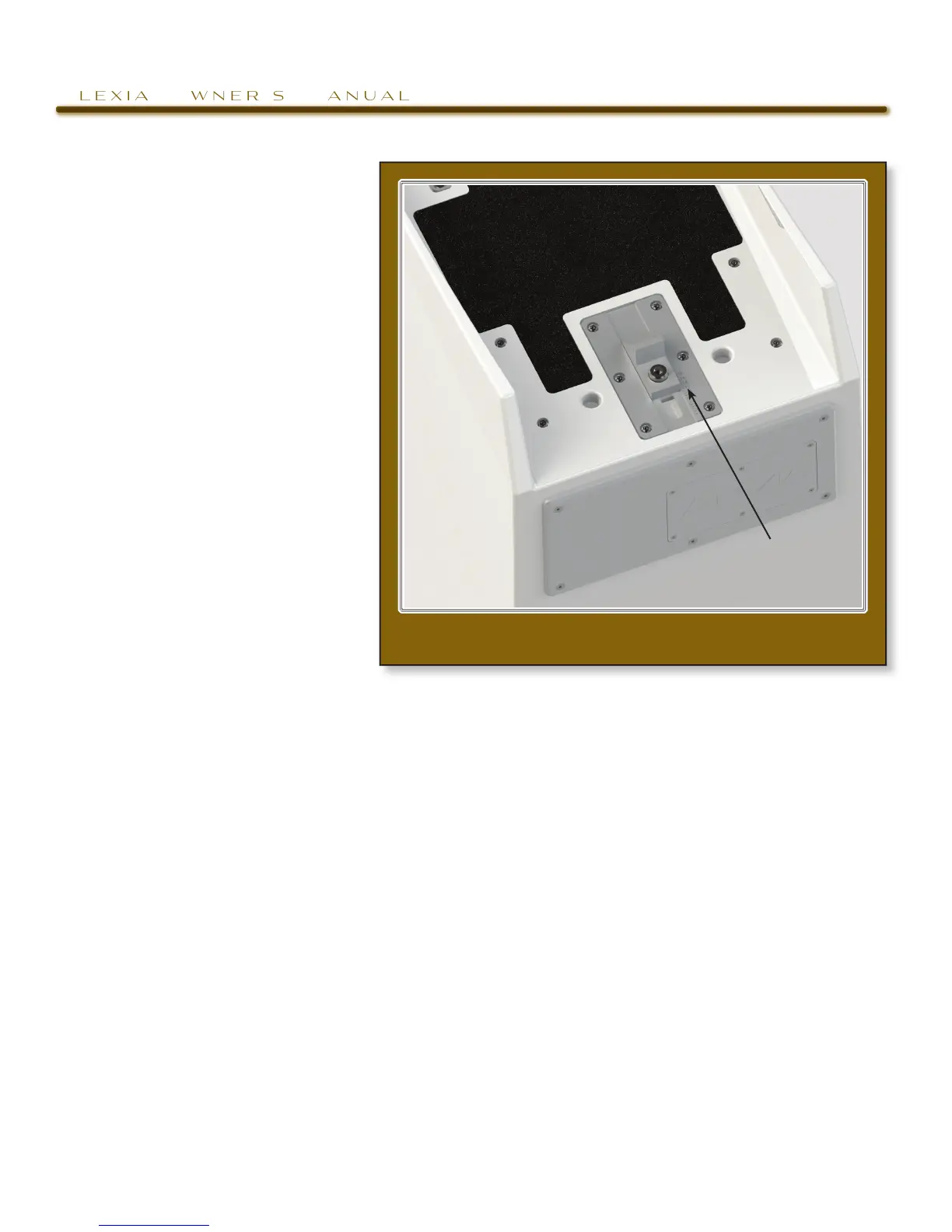
The Tweeter module’s upper plate features detents that correspond to a spike built
into the front of the upper cross member located above the tweeter module (see Fig-
ure 7), the specific location of which determines the propagation delay position of
the tweeter module within the Upper Array. The alignment plate contains numbered
indents. The alignment tables in Section 8 contain the information for positioning the
tweeter module in the array, determined by the indent in which the cross member’s
spike rests.
Determine the alignment of each Upper Array and the Tweeter Module as follows:
1. Repeat each step of this procedure on the left and right channels simultane-
figure 7—slide the AlignMent blOck tO its prOper pO-
sitiOn
AliGn tHe reAr of tHe Block
to tHe correct nUmBer