10
OPM-171/B
your application’s needs. Consult experts in this field for
assistance in designing this part of the system.
DANGER
Only use ASME pressure vessels. Do not use modified or
damaged pressure vessels because it can result in injury,
death and equipment damage.
An appropriately sized buffer tank is recommended for this
application. This will prevent the compressor from loading
and unloading rapidly extending the life of the equipment.
For most spray foam applications, a 30 gallon buffer tank is
sufficient. Consult your tank supplier for help calculating the
optimal buffer tank for your load profile.
All tanks, lines and valves must be installed in accordance
with the best safety practices with proper pressure relief,
vent and water drain valves.
DANGER
Failure to properly install pressure relief valves can result in
injury, death and equipment damage.
Rotating your air-intake on the compressor towards the
fresh air source can reduce your operating temperature.
You can plumb your air intake outside the enclosure as long
as your pipe is larger than the air intake on the compressor.
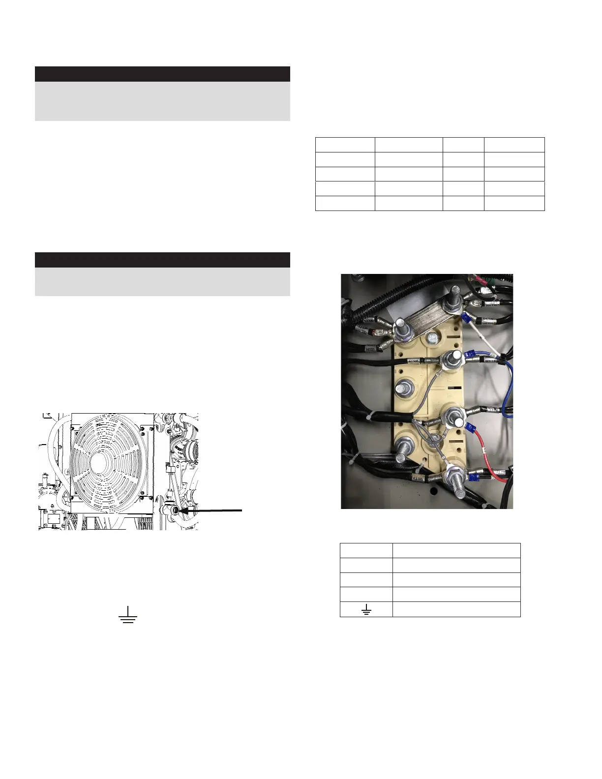
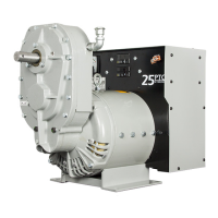
CONNECTING TO COMPRESSOR
Locate the 3/4” NPT on the air cooler (reference following
image) and attach your air hose.
ELECTRICAL CONNECTIONS
NOTICE: CLASS 1 WIRING METHODS ARE TO BE USED FOR
ALL FIELD WIRING CONNECTIONS TO TERMINALS OF A
CLASS 2 CIRCUIT
NOTE: The symbol always indicates ground where
shown. All wiring must be completed in accordance with
the National Electric Code as well as any state and local
codes.
You must pay particular attention to wire size requirement
for the amperage of service you are dealing with. The table
below provides you guidance on wire sizing based on
both wire type and amperage. Wire amperages have been
derated for 40° C ambient temperatures operation.
3/4” NPT
GENERATOR CIRCUIT BREAKER
This unit DOES NOT come with a circuit breaker. The circuit
breaker will provide overload protection for the generator.
The following table gives you the recommended circuit
breaker size specifications. See actual breaker for wire
capabilities and torque specifications and restrictions.
Watts Voltage Phase CB AMP
40,000 120/240 1 175-200
40,000 120/208 3 150-175
40,000 120/240 3 125-50
40,000 277/480 3 60-75
The wire must be properly sized between the generator
and the load. Use the table 310-16 of the National Electrical
Code ANSI/NFPA 70. to properly size the wire to meet or
exceed the amperage rating of the circuit breaker installed.
Lug size 10mm
CUSTOMER CONNECTIONS
U Line 1
V Line 2
W Line 3
N Neutral
Ground
The DSE 7310 controller uses current transformers (CT) to
monitor the amount of load on each leg of the generator. If
the wires are routed through the CT the wrong direction it
will result in a negative current readings on the controllers.
This can be corrected by swapping the wires on the CT
terminals in the generator end. Zip tie the wires to the CT
walls after installation in order to prevent wire movement.
N
W
V
U