11 OPM-171/B
DANGER: PERSONAL INJURY
These units are shipped with a NEUTRAL TO GROUND
BOND INSTALLED. If your system already has a neutral
to ground bond, then you must run a separate ground
lead to that location and UNBOND THE JUMPER IN THE
CONNECTION PANEL. For additional information, refer to
the current National Electrical Code on grounding.
WARNING: EQUIPMENT DAMAGE
When installing a three phase 240 Volt system, be sure
you know which lead is high voltage ‘wild’ leg (208 Volt to
neutral). The generator normally carries the high voltage
on the G2 lead.
GROUNDING
Proper grounding of your generator is application
dependent. Carefully evaluate your planned use of your
generator to understand which grounding you require.
If you are not sure what to do, contact a competent
professional to assist you. The NFPA 70 250:34-35 are good
technical references.
VEHICLE-MOUNTED GENERATOR
Your WINCO generator ships with a bonded neutral.
When mounted to a vehicle to safely distribute power it is
necessary that the generator frame is bonded to the vehicle
frame. The generator should only supply equipment that
is cord and plug connected through customer installed
receptacles mounted on the generator or the vehicle.
PERMANENTLY INSTALLED GENERATORS
This WINCO portable generator ships with a bonded
neutral. NFPA 70 refers to this as a “separately derived
system.” When connecting it to a building a transfer
switch specifically designed for GFCI and bonded neutral
generators is required or the ground or the neutral to
ground bond must be broken and the panel relabeled.
TRANSFER SWITCH
NOTICE:
For full service switching of the entire load, the ATS must
be ‘SE’ (Service Entrance) rated or must have a properly
rated fusible disconnect installed before the ATS to protect
the contacts.
WARNING: FIRE HAZARD
All wiring must be done by a licensed electrician, and must
conform to the National Electrical Code and comply with
all the local codes and regulations. Check with the local
authorities before proceeding.
INSTALLATION NOTES:
Because of many different types of service, feeder and
distribution equipment, no specific wiring instructions
can be provided. It is recommended that only copper
wire be used. In all cases it is essential that while the load
is connected to the generator, there can be absolutely
no feedback from the generator to the power line or the
power line to the generator. When properly installed, the
normal ATS Control and safety system will eliminate all
paths and feedback.
To wire the automatic transfer switch into existing wiring,
first determine which circuits will be on the emergency
load circuit. If the entire load is transferred, the transfer
switch can be wired directly after the meter and the service
entrance, providing the service entrance ampere rating is
within the transfer switch’s rated capability.
If only specific circuits are to be powered under emergency
power failure conditions, an additional distribution panel
designated “emergency distribution panel” must be
installed.
All selected emergency circuits are removed from main
distribution panels and installed in the emergency
distribution panel. The ATS is then installed between
the main panel and the emergency distribution panel.
Suggested circuits: freezer, refrigerator, furnace, emergency
lights, sump pump, emergency outlet circuits, etc. Total
running load must not exceed generator rating.
DC WIRING
CAUTION
Never run the AC and DC wiring on the same conduit.
REMOTE START
The DSE7310 is able to start the generator when it receives
a remote signal from any dry contact. This makes the system
compatible with a wide range of control mechanisms
including two-wire start automatic transfer switches. When
the contact closes the controller will automatically start.
When the contact is opened the generator will go through
a cool-down cycle and turn off. Connect the remote start
leads to the Remote Start + and Remote Start - terminal
blocks in the door behind the DSE 7310 controller.
E STOPS
In some applications additional emergency stops may be
desired or necessary. The controller has terminals designed
allowing the addition of multiple remote emergency stops.
E-stops must be normally closed to work properly in this
system. The e-stop circuit supplies power to fuel solenoid
and the starter circuit. Opening any switch in the series
prevents the engine from cranking or from receiving fuel to
run.
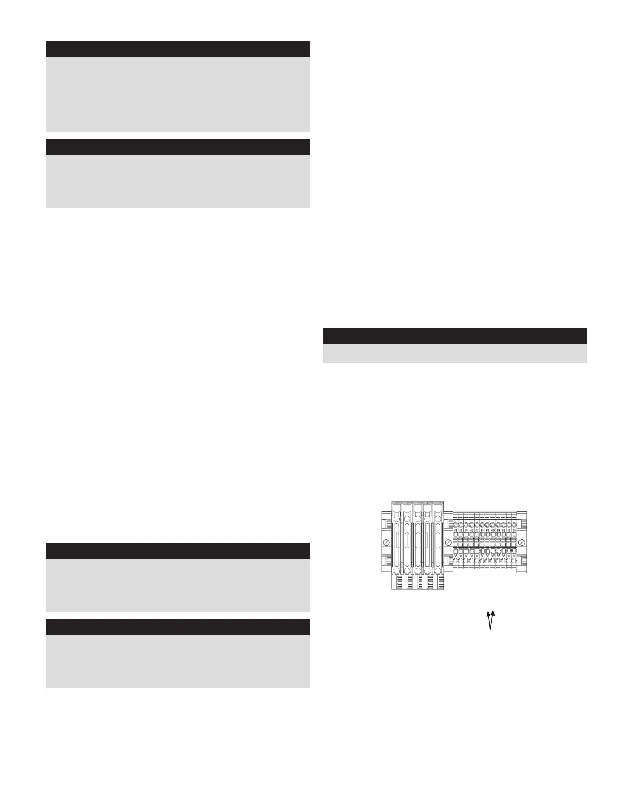
SCR (DSENET)
4A (DSENET)
4B (DSENET)
Battery Charge Fail
Emergency Stop
Emergency Stop
Remote Start +
Remote Start -
Ground
Ground
Battery +
Battery -
Two-Wire Start Hook-Ups