17 OPM-171/B
With the engine running smoothly check the no load
voltage and frequency on the digital display. The
voltage should match the nameplate and a frequency
of 59.5 to 60.5 hertz (Hz).
If you have the proper voltage at the generator the
next step is to check the voltage at the generator
terminals in the Automatic Transfer Switch. The voltage
between the G1 and the G3 terminals should be the
same as it was on the generator front panel. The
voltage should also be checked between the hot
terminals (G1 and G3) and the G-N to be certain of a
balanced voltage output and a solid neutral
connection. The voltage between G1 and G-N should
be about 120 volts AC (277 on 480 units). The same
approximate voltage should be found between
terminals G3 and G-N (120 volts AC).
On three phase panels the G2 voltage level should also
be checked. ON 240 VOLT (DELTA) SYSTEMS BE SURE
YOU KNOW WHERE THE HIGH VOLTAGE “WILD” LEG
IS. IT MUST BE IN THE SAME LOCATION ON THE LINE
SIDE AS IT IS ON THE GENERATOR SIDE. (i.e. if it’s on
L-3 on the line side it must be on G-3 on the generator
side. Also on three phase systems make sure that the
rotation is the same on the generator as it is on your
line power. Failure to insure proper rotation will cause
three phase motors to spin backwards possibly
damaging them.
NOTICE: If for any reason during the check out procedure
the voltage and frequency are not correct, depress the
STOP/RESET button and correct the trouble before
proceeding.
4. Stopping - There are two ways to stop the unit when it
is in the manual mode. Pressing the STOP/RESET
button will stop the unit immediately. Pressing the
AUTO mode button will stop the unit but only after the
cool down timers have timed out and there is no
remote start signal being sent to the unit.
WARNING: EQUIPMENT DAMAGE
Always make sure the generator runs under no load for
five minutes before stopping to allow the engine and
components to cool down. Don’t use the E-Stop to shut
down the generator unless there is an emergency.
CONTROL POWER
The DSE7310 controller consumes small amounts of battery
power when it is in use. The controller comes with a power
switch that disconnects battery power when it is not in use.
The switch is designed with a safety relay that prevents it
from removing power to the controller while the generator
is operating. If the switch is turned off while the engine is
running it will continue operating until the engine shuts
down and then the controller will power down.
This switch should be used when the generator is not
going to be used over the course of several days and the
generator is not connected to a battery charger.
A solar charger kit is the easiest way to always maintain the
battery during storage in mobile applications. The supplied
battery charger can be plugged in to an extension cord on
mobile applications.
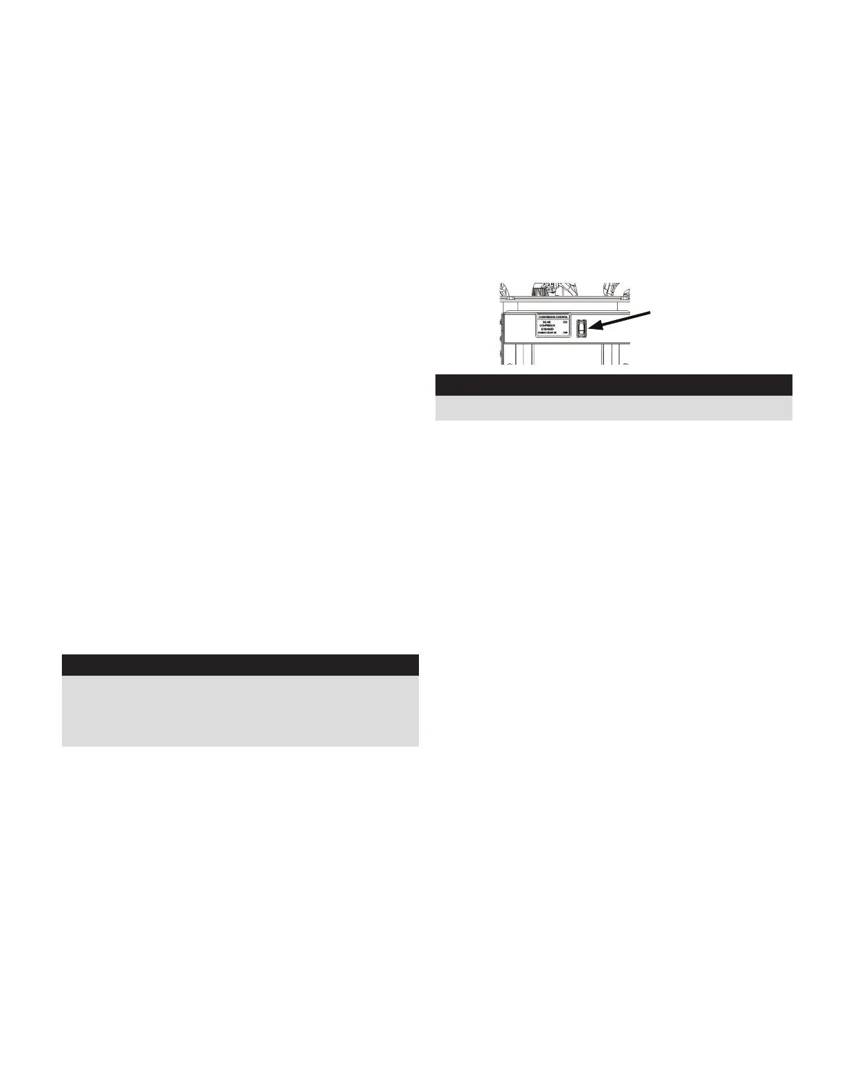
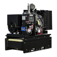
COMPRESSOR START UP
This unit has been equipped with an air compressor that
uses an auxiliary shaft from the generator to provide 120
PSI @ 40 CFM.
START UP
Follow the starting procedure found previously in this
manual.
Once the engine is running at speed, engage the air
compressor toggle switch, located next to the control panel,
to the ‘on’ position.
WARNING: EQUIPMENT DAMAGE
Always start and stop engine with the air compressor OFF
Air compressor
toggle switch