Marine Installation Manual 2021-08 3-17
3 Engine Installation
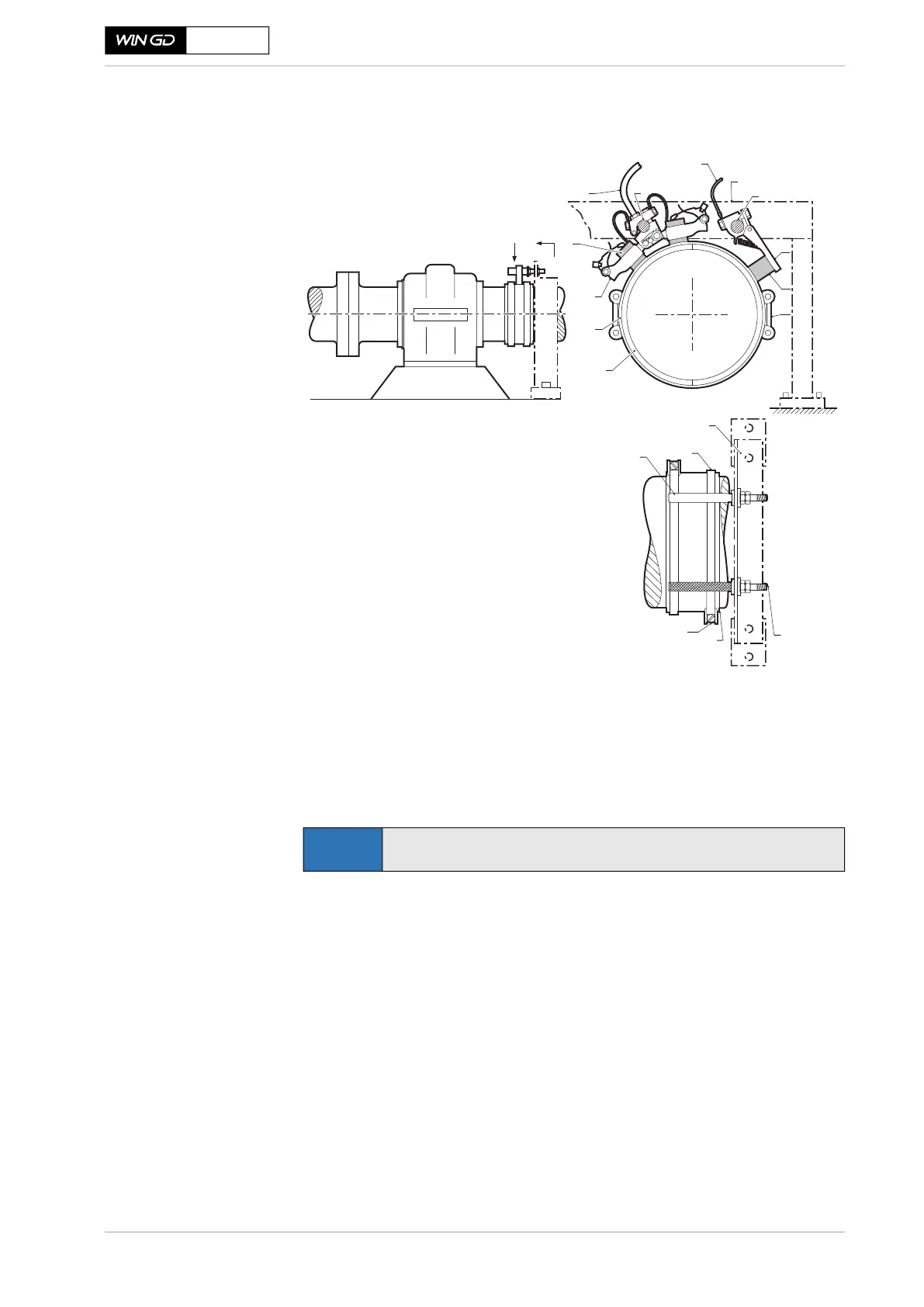
3.10 Propulsion shaft earthing
X72DF
Figure 3-4 Typical shaft earthing arrangement
Position of earthing
device on shaft
The earthing device has to be arranged as close as possible to the engine. In case
a shaft generator /motor is installed, the earthing device has to be arranged on
the front side of the generator/ motor, as close a possible to the engine.
Connecting
electric cables
The electric cables are connected as shown in Figure 3-5, 3-18 with the op-
tional voltmeter. This instrument is at the discretion of the owner, but it is useful
to observe that the potential to earth does not rise above 100 mV.
Typical arrangement for the propeller shaft
A
A
1
2
3
4
5
6
7
8
9
10
11
12
Slip ring
Tension bands
Twin holder
Brushes
Connection to the ship’s hull
Steel spindle
Connection to the voltmeter
Mounting bracket
Insulated spindle
Single holder
Monitoring brush
Clamps
View on ‘A’ (brush gear omitted)
NOTE
For detailed information please contact the earthing device supplier.