Instructions premix Air heaters type XR10.. 60 Page 15/15
1
2
3
4
5
6 7
8
9 10
11
12
13
14
J2
J1
X2
Hall sensor
PWM
Gnd
24 Vdc
2
5
4
1
-T
X6
X5
X4
Room Thermostat
Sit DBC 577
DFC 100
1
2
3
4
5
6
1
2
7
3
8
5
10
4
9
2
4
6
7
3
1
5
8
20°C
STB
NTC 20KOhm 25°C
X
6
-
7
1
2
3
7
4
5
6
41 2
3 5 6
7 11 12
M1 (N)
24V gnd
M1 (L)
L (230 Vac)
X
2
-
9
X
2
-
4
X
2
-
1
0
X
6
-
2
X
6
-
4
1
X4
2 3
4
5 1
X5
1 2
3
2 3 4 5
X6
6 7 8
4
2
P1
P2
49
10 5
7
8
2
3
6
1
3.15AT
F1
RE2 RE3
X2
IC
X3
3
1
X1
RE5
RE4
RE6
RE1
DFC 100
2AT
F2
Code 0.577.406
1 2 3 4
EV2
EV1
M2
X7
X7
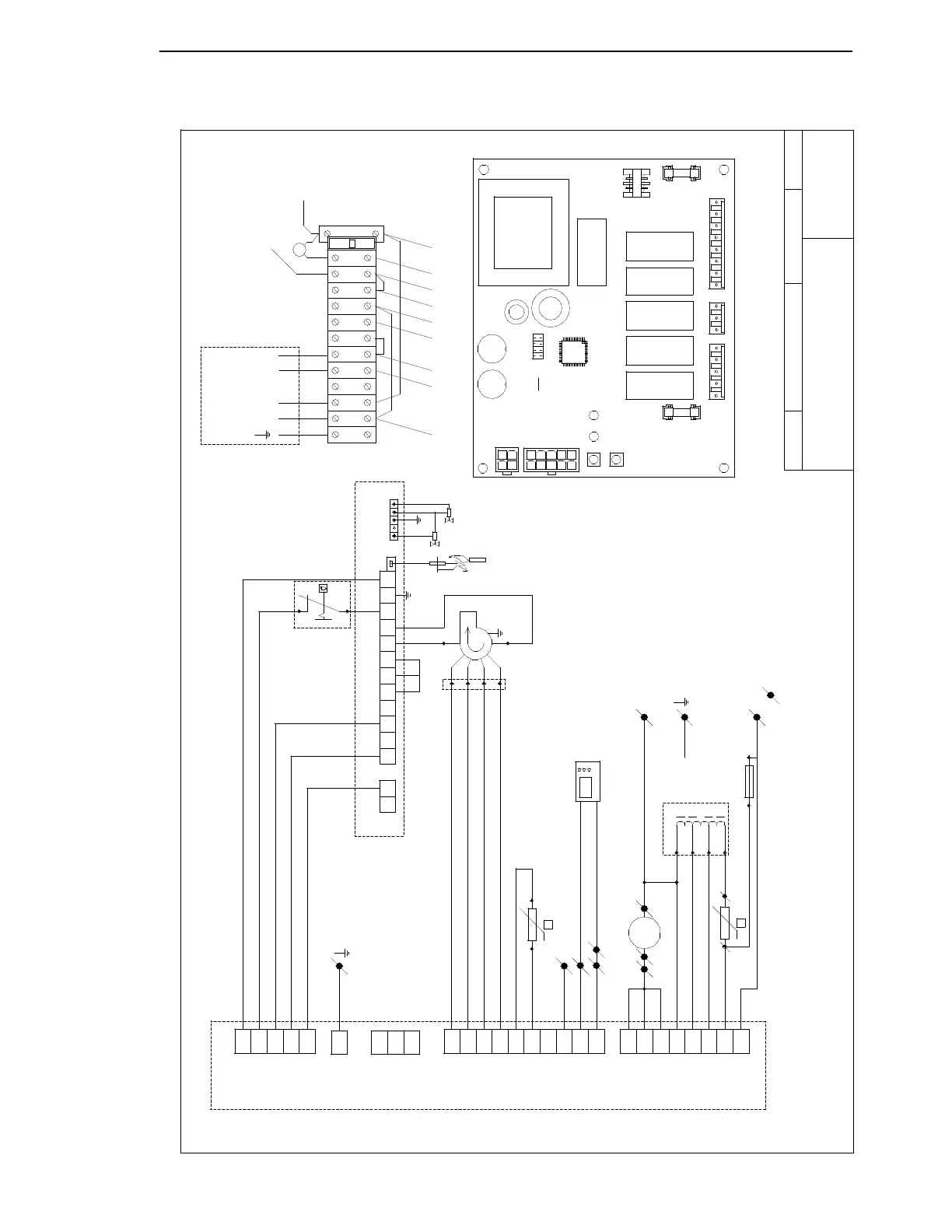
External reset: make contact between connection 6 and 7
EV1/ 2
Gas valve
Transformer for Fanregulation
Fuse
TR1
F
Pre mix fan
Connections for installation purposes
Limmit thermostat (manual reset)
3
Fan motor
STB
M1
M2
n
F3
M1
1~
white
red
braun
braun
black
black
blue
black
12
13
grey
-T
14
blue
11
TR1
L (230V AC)
1
N (Neutral)
2
X6-5
X
6
-
8
13 14
F3
X6-6
violet
transp.
black
black
blue
orange
black
yellow
grey
yellow
red
black
blue
green/yellow
Room thermostat (Open therm or ON / OFF)
black
blue
For installer
Room
Connections
T
R
1
g
r
e
y
Thermostat
Reset (to gnd 24V)
T
R
1
b
l
a
c
k
N (neutral)
GB
Reset
Service
Red
Green
Reset
DBC ON
Alarm
Fan Medium
Fan Low
Fan High
NTC 10 Ohm 25°C
N
(type 50: 160 V)
180 V
230 V
1
2
3
type 10-30: 1.25 AT
type 40-60: 3.15 AT
140 V
or black
Auth.:
Titel: Schema N°:
Get.:
Datum:
R-series type 10 - 60 230V
R101c
MF
26-01-2005
green
$ #$#+#/
$ #$#+#/$ #$#+#/
$ #$#+#/
 Loading...