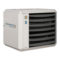
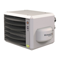
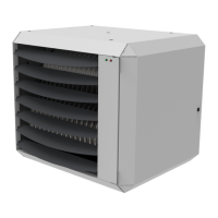
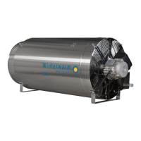
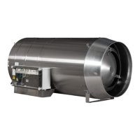
This document describes the Winterwarm Air Heater Type XR, a gas-fired air heater designed for space heating. It is intended for installation, use, and maintenance by qualified gas, electrical, and mechanical installers. The manual emphasizes adherence to national and local building, health, and safety regulations, as well as specific gas safety and electrical installation requirements.
Function Description
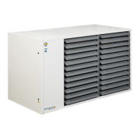
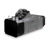
The Air Heater Type XR is a heating appliance that uses gas combustion to generate heat, which is then distributed into a space via a system fan. It is designed to provide efficient space heating and can also function as a de-stratification fan to ensure even temperature distribution. The heater is controlled by a room thermostat, offering both modulating and ON/OFF control options.
Key operational features include:
- Burner Cycle: The heater operates through a defined burner cycle, including stand-by, pre-check, pre-purge, pre-ignition, ignition, flame check, burn (modulating from high to minimum power), burner off, and post-purge phases. The display on the heater indicates the current status of this cycle.
- Minimum Firing Time: To prevent frequent starts and stops and to avoid condensate accumulation in the flue system, the heater has a minimum firing time of 4 minutes.
- Delta-T Regulation: This feature allows the air heater to act as a de-stratification fan. The system fan activates when the temperature difference between a sensor on the heater (delta-T NTC sensor) and the room thermostat sensor exceeds 8°C (standard setting). This ensures uniform temperature distribution throughout the building. This function can be switched off if not desired.
- Summer Ventilation: The fan can be set to run during summer for ventilation purposes, controlled via the room thermostat.
- Overheating Protection: The heat exchanger and flue system are protected from excessive temperatures by NTC sensors. In case of overheating, the heater will reduce power, stop the burner, and may require a manual reset.
- Flue Passage Check: A pressure switch monitors the passage of combustion air through the heat exchanger during the pre-purge phase. Insufficient pressure difference will prevent the heater from starting, indicating a potential blockage.
Important Technical Specifications
The Air Heater Type XR is available in several models (XR10, XR20, XR30, XR40, XR50, XR60), each with varying performance characteristics.
General Specifications (Type XR-4.1, ERP2018):
- Heat Input (Net Nominal): Ranges from 14.0 kW (XR10) to 66.0 kW (XR60) at max power, and 9.0 kW (XR10) to 39.6 kW (XR60) at min power.
- Heat Output: Ranges from 12.8 kW (XR10) to 60.5 kW (XR60) at max power, and 8.3 kW (XR10) to 37.0 kW (XR60) at min power.
- Efficiency: High efficiency, typically above 90% at both max and min power (e.g., XR10: 91.4% max, 91.7% min; XR60: 91.7% max, 93.4% min).
- Seasonal Space Heating Efficiency: Ranges from 72.8% to 76.3%.
- Air Output (Max.): Ranges from 1150 m³/h (XR10) to 6300 m³/h (XR60).
- Throw (Horizontal/Vertical Warm): Horizontal throw ranges from 12m (XR10) to 30m (XR60); vertical throw ranges from 5m (XR10/20) to 8m (XR60).
- Gas Connection: 1/2" for XR10-30, 3/4" for XR40-60.
- Electrical Connection: 230 V (50 Hz).
- Electrical Power Consumption (Max.): Ranges from 0.250 kW (XR10-30) to 0.600 kW (XR60).
- Electrical Current: Ranges from 1.1 A (XR10-30) to 2.6 A (XR60).
- Protection Class: IP00B (not waterproof).
- NOx Emission (GCV): Ranges from 35 to 43 mg/kWh, NOx class 5.
- Chimney Flue Pressure (Max.): 90 Pa (XR10-30), 120 Pa (XR40-60).
- Sound Level (at 8m): Ranges from 42 dBA (XR10) to 49 dBA (XR60).
- Weight: Ranges from 36 kg (XR10) to 82 kg (XR60).
Gas Types:
- Natural Gas G20: Nominal supply pressure 20 mbar (min-max 17-25 mbar). CO₂ High: 9.0-9.1%, CO₂ Low: 8.5-8.8%. O₂ High: 4.9-5.1%, O₂ Low: 5.8%.
- Propane G31: Nominal supply pressure 30-50 mbar (min-max 25-50 mbar). CO₂ High: 10.3-11.1%, CO₂ Low: 9.9-10.7%. O₂ High: 4.7-5.0%, O₂ Low: 5.7%.
Usage Features
- Installation Flexibility: The heater can be installed with various wall supports (standard, turnable, vertical suspension kit, suspension adapter) depending on the model and desired orientation. Minimum clearances around the heater must be maintained for safety and service access.
- Room Thermostat Control: The heater is designed to be controlled by Winterwarm modulating room thermostats (MTS, MTC) or an interface module for BMS systems. A simple ON/OFF thermostat can also be used.
- Multi-Heater Control: An MTC or MTS thermostat, or interface module, can control up to 8 air heaters, each requiring a unique number set via switches on the control unit.
- Flue System: Requires connection to a CE-marked flue system (Muelink & Grol or Burgerhout, type Alu-fix T250 P1). Flue terminals are available for vertical (roof) or horizontal (wall) discharge. Maximum straight flue length is 9 meters. Condensate discharge or insulation may be required for long flue pipes or cold environments.
- Gas Valve Adjustment: The gas valve can be adjusted for high and low power settings to control gas flow to the burner, with CO₂ or O₂ in flue gas monitored by a calibrated analyzer. This ensures optimal combustion efficiency and prevents toxic carbon monoxide production.
- Gas Type Conversion: Conversion to another gas type must only be performed by the manufacturer or its representative.
Maintenance Features
Regular maintenance and cleaning are crucial for safe and proper operation, and to maintain warranty validity.
Preparation for Maintenance:
- Set the thermostat to the lowest setting.
- Close the manual gas valve.
- Turn off the power supply using the maintenance switch.
- Always check for gas leaks after working on the air heater.
- The heater must be electrically isolated during servicing.
- Do not use water for cleaning electrical parts.
Basic Maintenance (Annually by a qualified installer):
- Inspection and Cleaning:
- Inspect the outside of the heat exchanger.
- Clean the fan guard and fan blades.
- Open the access panel and clean the inside of the heater, focusing on the body, fan blades and motor, heat exchanger, temperature sensor, and vane switch (if present).
- Use a dry cloth, brush, compressed air, or vacuum cleaner; never a steel brush.
- Checks:
- Verify that wiring, nuts, and bolts are properly secured and tightened.
- Grease any parts and bolts regularly loosened for maintenance.
- Open the manual gas valve and check supply lines for airtightness and absence of air.
- Reconnect power, switch on the heater, and check for proper operation and absence of errors.
- Check combustion efficiency and adjust burner settings if necessary (CO₂ value).
Burner Unit Maintenance:
- Remove the gas pipe between the gas valve and combustion fan.
- Remove ignition and fan wires.
- Unscrew socket screws (M6).
- Remove the burner unit (with flange and pre-mix fan) from the air heater.
- Disassemble the burner unit.
- Adjust Ignition Electrode:
- Check the distance between the electrode and the burner (5 ±0.5 mm).
- Check the distance between the two electrodes (3.6 ±0.4 mm).
- Ensure the spark forms between the two electrodes, not between an electrode and the burner.
- Reassemble the burner unit using new gaskets and reinstall it in the air heater.