24
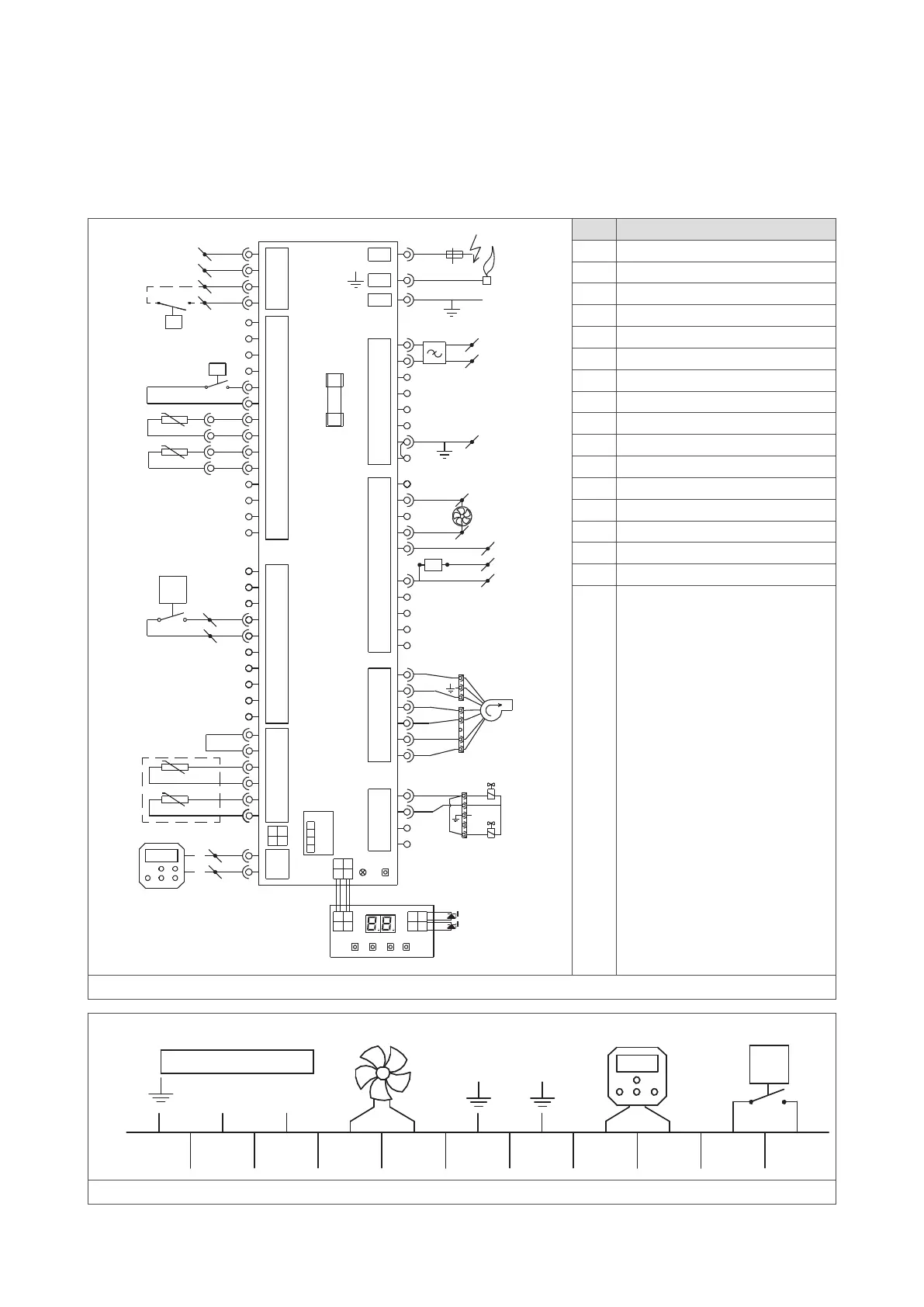
11 Electrical wiring diagram
A complete electrical wiring diagram is shown in figure 25. The connections that are most important to the installation
process are shown in figure 26.
20K@25°C
22°C
L
N
F1: 5AT
20K@25°C
20K@25°C
J9- 1
J9- 3
J9- 2
J9- 4
J6- 1
J6- 8
J6- 2
J6- 9
J6- 3
J6- 10
J6- 4
J6- 11
J6- 5
J6- 12
J6- 6
J6- 13
J7- 1
J7- 2
J7- 3
J7- 4
J7- 5
J7- 6
J7- 7
J7- 8
J7- 9
J7- 10
J12- 1
J12- 4
J12- 2
J12- 5
J12- 3
J12- 6
J8- 1
J8- 2
J6- 7
J6- 14
T1
J2- 1..6
J1- 1
J1- 5
J1- 2
J1- 6
J1- 3
J1- 7
J1- 4
J1- 8
J3- 2
J3- 6
J3- 1
J3- 7
J3- 3
J3- 8
J3- 4
J3- 9
J3- 5
J3- 10
J4- 2
J4- 3
J4- 5
J4- 4
J4- 1
J4- 6
J5- 1
J5- 2
J5- 4
J5- 3
4
3
1
2
J25
LED RESET
4
3
1
2
4
3
1
2
PE
L triac
11
12
N
L
5
4
J17
100K@25°C
7
6
J2
L
N
5
4
3
2
1
4
3 1
2
J16
4
3
1
2
A/+
24V
B/-
GND
20 (GND)
21 (0-10V)
dP
C2
C3
C4
C6
D1
D2
E1
I1
M2
M3
P1
S2
T1
T2
T4
V1
PE
K6
K6
11
13
Modbus
9 (A1)
10 (A2)
A1
8 (N)
K6
A1
A2
RT
No. Connection type
A1 Alarm output 230 V (optional)
C2 Modbus connection (optional)
C3 0 - 10 V input (optional)
D1 Display (2 x 7 segment)
D2 Red and green LED
E1 Power line EMI filter
F1 Glass fuse (5 x 20 mm 5AT)
I1 Ignition/ionisation electrode
K6 External reset (optional)
M2 Modulated system fan (triac)
M3 Pre-mix fan
P1 Power supply (230 V)
S2 Pressure switch (combustion)
T1 Temperature sensor (heat exchanger)
T2 Temperature sensor (flue) (optional)
T4 Temperature sensor (delta-T)
V1 Gas valve
Figure 25 - Electrical wiring diagram AC
RT
N
L
230 Vac
L
N
22°C
Figure 26 - Main connections for installation