Manual 35018V1 505XT Digital Control System for Steam Turbines
Woodward 183
Event
ID DESCRIPTION MEANING
44 External Trip 14 External Trip #14 contact input was opened
45 External Trip 15 External Trip #15 contact input was opened
46 spare_46 reserved for future use
47 spare_47 reserved for future use
Each individual trip condition is available through the Modbus links to monitor the control status. A
common trip indication is also provided.
Relay indications can be programmed to indicate a 505 Shutdown Condition (energizes for a shutdown
condition) or a Trip Relay (de-energizes for a shutdown/trip), in addition to the dedicated Emergency Trip
Relay output.
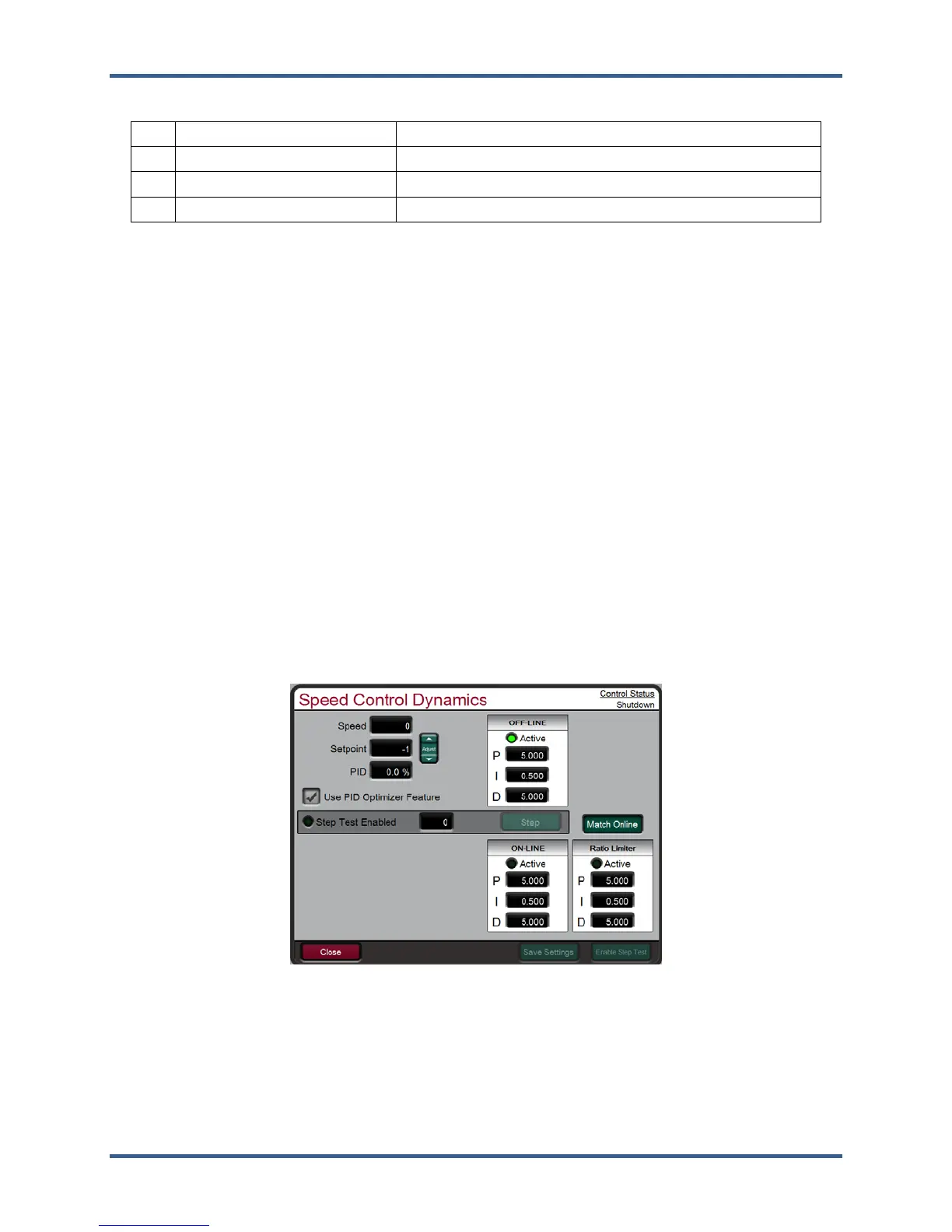
Manual Dynamic Adjustments of Speed, Cascade, Auxiliary, Inlet,
Exhaust and Ext/Adm Controls
This section will cover the basics of the manual tuning of the PID dynamics that need to be performed
initially on the unit. Only the speed control loop is used on every system, the other controls need not be
tuned if they are not configured for use. For the speed and extraction control loops the OPTI tune feature
is available to calculate idea dynamic settings for the overall system. Refer to the OPTI Tune section of
this manual.
Dynamic control values are programmed in the configuration mode and adjusted in the RUN (Operation
or Service) mode. The Proportional and Integral Gain and the Derivative Ratio dynamic adjustments are
available under found under Dynamics pages for each controller (SPEED, CASC, AUX, INLET,
EXHAUST and EXT/ADM). To adjust the gain settings, the In-Focus highlighter must be on the
component value to tune. The In-Focus highlighter is moved using the navigation Cross. The ADJUST UP
and DOWN keys can then be used to adjust the function In-Focus.
Figure 5-32. Speed Dynamics Adjustment Screen
The Speed, Cascade, Auxiliary, Inlet, Exhaust and Ext/Adm controls are PID controllers. The response of
each control loop can be adjusted by selecting the dynamics mode as described above. Proportional
gain, integral gain (stability), and DR (derivative ratio) are the adjustable and interacting parameters used
to match the response of the control loop with the response of the system. They correspond to the P
(proportional), I (integral), and D (derivative) terms, and are displayed by the 505 as follows:
 Loading...