Manual 35018V1 505XT Digital Control System for Steam Turbines
Woodward 32
Input Power Specification
Specifications (LV)
LV Input Voltage range: 18-36 Vdc
Input Power (max): < 77 W, 4.3 A max
Output Voltage Holdup time: > 14 ms with 24 Vdc input voltage
Isolation to other circuits: > 500 Vrms to all other circuits
Isolation to EARTH: > 500 Vrms to EARTH
Input Overvoltage Protection: ±60 Vdc @ 25 °C
Reverse Polarity Protection: 60 Vdc @ 25 °C
Input Undervoltage shutdown: ~11 Vdc, non-latching
Note: Breaker or power-line fusing of 8 A min is recommended to protect the power wiring network
from possible wiring shorts.
Specifications (HV)
HV Input Voltage range: 88-264 Vac / 90-150 Vdc
HV Input Frequency range: 45-65 Hz
Input Power (AC max): < 73 W, 1.6 A max
Input Power (DC max): < 73 W, 0.8 A max
Output Voltage Holdup time: > 30 ms with 110 Vac input voltage
Output Voltage Holdup time: > 120 ms with 220 Vac input voltage
Isolation to other circuits: > 3000 Vrms to all other circuits
Isolation to EARTH: > 1500 Vrms to EARTH
Input Overvoltage Protection: ±375 Vdc @ 25 °C
Reverse Polarity Protection: 375 Vdc
Input Undervoltage Shutdown: ~65 Vdc, non-latching
Note: Breaker or power-line fusing of 3.5 A min is recommended to protect the power wiring network
from possible wiring shorts.
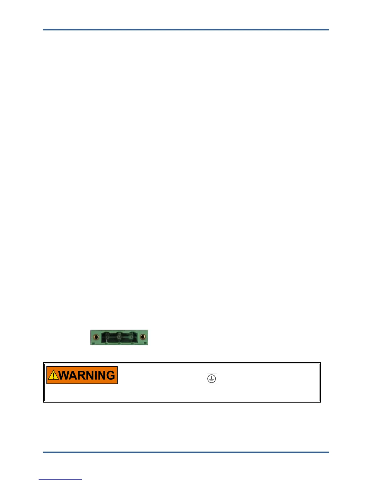
Power Connector
Input Power is provided through a 3 position, latching terminal block with removable plug. Green
connectors are used for low voltage DC units. Orange connectors are used for high voltage AC/DC units.
Table 2-2. Input Power Connector Pinout
Board Connection PIN Name Description
1 L+ Input Power (+)
2 L- Input Power (–)
3 EARTH Earth / shield connection
Plug Type: Side entry 7.62 mm, 12 A, pluggable with latching screw down
Electric Shock
To reduce the risk of Electrical Shock the Protective Earth (PE)
must be connected to the PE terminal on the enclosure. The
conductor providing the connection must have a properly sized
ring lug and wire gauge equal to or larger than 4mm² (12AWG).
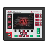
Visual Indicators (LED’s) & CPU Configuration
Visual indicators are located on the Front Panel keypad, the controller board, back cover, and related
communications ports for diagnostic use.
 Loading...